[Plugin] Extrude Edges by Rails
-
It takes the nearest points of the rails to place / adjust the profile.
Split the square's edge nearest the circle at it's center.
It should then not twist ? -
@tig said:
It takes the nearest points of the rails to place / adjust the profile.
Split the square's edge nearest the circle at it's center.
It should then not twist ?Thank you for the advice, however It seems no possible.
By the way I can ever achieve the good result with the previous method.
Maybe it would be nice an option to set the starting point.
It could work well in conjuction with tool on surface I think.By the way I think your plugin is quite revolutionary.
thanks again.
Ionandre
-
Sorry, I don't think my last explanation was very clear.
As explained in the Tool's notes... if the Profile touches a Rail then that fixes the Profile's 'snap-point' on that Rail: it is the safest way to fix what's made - otherwise you can be surprised - like this 'twisted' extrusion.

So it if touches both Rails then that fixes the Profile without twists - sorted.
But like in your case - if the Profile doesn't touch Rail-1 then the snap-point for the Profile on Rail-1 is taken as the point nearest to the end of the Profile - unfortunately in your case Rail-1 [the square] has 4 points that are all 'nearest' to the centred Profile's start [this is after the Rail is sub-divided into parts to match the Circle]. Therefore the Tool guesses at the start of Rail-1...
Next, as in your case - if the Profile doesn't touch Rail-2 then the snap-point for the Profile on Rail-2 is taken as that point nearest to the end of the Profile; however, in your case it's a circle so all of its Vertices are equidistant from the Circle's center [the Profile's other end] ! So in this case it takes the snap-point as the one nearest to Rail-2 - and that's the bottom of the circle...
Now the Profile is snapped to that point and a point on Rail-1 - which can be guessed as any of 4 points - giving a 4:1 chance of a twisted extrusion being made...
 Simple fix... the Profile's path is not change if it is relocated... So Move the Profile so that it's end is very near to the bottom Vertex of the Circle-shaped Rail... Pick that, then Pick the Circle-shape as Rail-1 then Pick the Square-shaped Rail... It should make an non-twisted extrusion.
Another way is to Divide the four edges of the Square-Rail into halves [so it then has 8 segments], then Move the Profile so it snaps to the Square's edge's mid-point that is nearest to the bottom of the Circular Rail, and then Weld the Square's 8 segments into a Curve... Run the Tool, Pick the Profile, the Pick Square-Rail, then Pick the Circle-Rail... Again it should make an extrusion that's not twisted...
-
Tig, would it be possible to make your plugin so one could lasso select the rails, eliminating the need to weld them ahead of time? i ask because it seems the weld script is kind of finicky and sometimes requires some effort to get the desired results.
-
Why is Weld so difficult - select the edges, weld them [answer No to any prompts], done ?
You'd need to select the edges with your method anyway - my plugin needs three curves - therefore weld some edges to make one if you need it...

-
weld doesn't always work, sometimes i have to do some creative things to get it to work, ie allow it to make a face then delete or explode parts of the curve then weld!
-
@xrok1 said:
weld doesn't always work, sometimes i have to do some creative things to get it to work, ie allow it to make a face then delete or explode parts of the curve then weld!
yeah, i get that too.. especially if i'm far along in a model and have used a lot of rubys prior to trying to weld.. i just save the file then reopen it.. weld seems to like the fresh start
-
Ok, now I have clear how it works. thanks.
Best option for me is to divide polygons in two welded halves. It doesn't take too long.
Moving profile can be an option for a different result. I mean the extrusion is good but with a different form.
By the way for what I have experimented until now, the last version (3.0) of the weld tool always work for me. I did notice some problem only with old version of this plug-in. -
I you are trying to weld bits of curves together into one bigger curve then right-click context menu explode-curve first so that weld has raw edges to work with.
Weld will sometimes make curves with unexpected vertex order - another fix for that is to select the curve and groups it then explode the group, often that will sort it out. Again if the curve has no edges using edit-cut and imemdiately paste-in-place can reorder the vertices correctly...
If you think about it EEbyRails using some weld type algorithms to sort vertices for mesh-making, these can occasionally [mercifully very rarely!] go wrong too. If the model's data-base is a little confused picking separate edges for EEbyRails would produce as much flakiness as welding them into curves first off !

For the foreseeable future EEbyRails will require three curves to work (or two if rail1==rail2)...

-


why is it that when i try the plug in this is what i got, no success at all.
-
Pretty Slick! Thank you, TIG.
1- Debabilizer. I am not sure but I think it is causing SU to load a lot slower. If it is not absolutely necessary, could a test be done in which it is not used to see of SU loads faster?
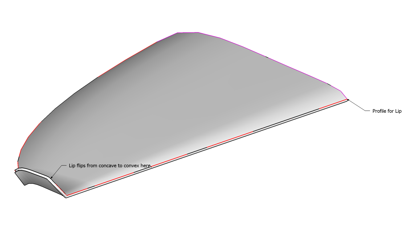
2- See attached. I used the colored edges to produce the top part of this swept wing. Then used joint-push-pull to creat the lower surface and then deleted extruded "side-surfaces" made by J-P-P. I wanted to see if make a rounded "lip" and along the two surfaces using Edges by Rails, but this is as good I could get it (I tried various combination of subdividing the edge rails, but the results were worse in most cases). How could a convex lip be formed along the edges of the wing?
-
I've tested
DeBabelizermyself and I seem to get no significant speed affects - db only kicks in whendb"text"is to be shown - however, renaming the ...EN-US.lingvo file will stop it being read at all, and so it might marginally speed it up - It won't affect anything else if you are using ENglish anyway ?
Alternatively you could always edit the script itself and do a find and replace for "db">>"", but leave thedef db()...end#defalone...I think you probably need to use vanilla
FollowMeor perhaps 'FollowMe and Keep' to make these rounded edges -EEbyRailsis perhaps too complex for this ? -
@dicoy88 said:
why is it that when i try the plug in this is what i got, no success at all.
Are you using the latest version?
Have you made three Arcs or Welded the Edges into Curves?The form you have shown works readily...SimpleEEbyR.skp
-
@tig said:
@dicoy88 said:
why is it that when i try the plug in this is what i got, no success at all.
Are you using the latest version?
Have you made three Arcs or Welded the Edges into Curves?The form you have shown works readily...[attachment=1:3p46zpil]<!-- ia1 -->SimpleEEbyR.skp<!-- ia1 -->[/attachment:3p46zpil][attachment=0:3p46zpil]<!-- ia0 -->SimpleEEbyR.png<!-- ia0 -->[/attachment:3p46zpil]
Yes i've done it all exept that im still using the SKP6. I didnt use SKP7 yet coz my Vray is for Skp6.
-
It should work OK with v6 and v7...
I no longer have v6 available after a HD fry-up!
Please try the thing again, but with the Ruby Console open and send us any errors that get reported - they might help pinpoint the problem and fix it... -
John, would you kindly explain the steps you are following to get that result?
Thanks. -
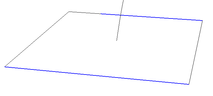
Thanks John. The step I was getting confused on was dividing the legs of the square (rectangle). The skp you posted came in un-welded and a bit disjointed which added to my confusion. See image. I got it now. This is a much welcomed script, thanks TIG. And thanks again John.
-
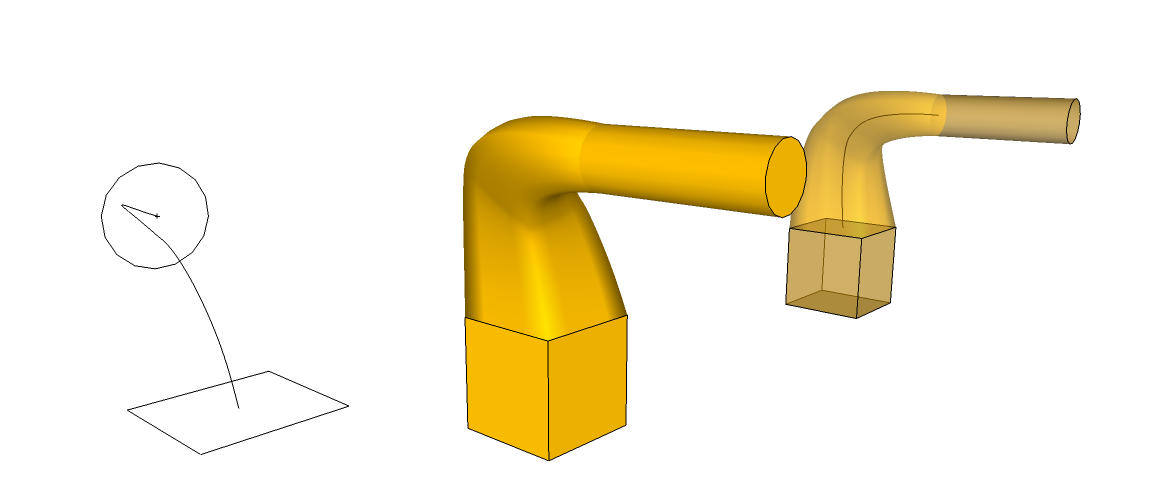
- Create circle, be conscious of the number of segments (use a multiple of 4). This one has 16 segments.
- Create rectangle and divide each edge into 4 segments. Select all 16 edges and weld.
- Position and rotate circle.
- Add a few constuction points to define where a connecting curve would have to bend 90° (you could carefully determine specific locations, I just guesstimated), these will serve as snapping points for Steps 5 and 6.
- Use the BezierSlineCurve script to draw a "Classic Bezier curve" from center of circle to a "halfway point" between it and the square. Draw a second bezier curve from that point down to the center of the square.
- Explode each bezier curve. Select the resulting segments and Weld them to form a path (actually a "Profile" per the terminology of TIGs script.
- Run the TIGs script. Select the select the path, the rectangle and the circle are to be regarded as "Rails" so click on each once.
- Answer the script prompts. Answer "No" to the last prompt to "Erase Original Lines".
- Select the square and add a face. Do the same for circle. Extrude both.
-
TIG,
I hope people appreciate what this script is capable of.
Think of the time it would take to create something like this without it.
[EDIT] the attached .skp has been update with a welded, 16 segment square.
-
Actually I do appreciate the confusion between 'Profile' and 'Rails' !
Think of the 'Profile' as the thing that is repeated around the Rails, and and the Rails the Curves that are followed.
On this example the central curved 'Path' is actually the Profile and it is repeated around the two Rails formed by the Square/Circle !!!To get another perspective on this think of the Square and Circle Curves as the Rails - i.e. the Paths to be followed.
Now copy your central 'Path' curve and snap its top-end to the bottom vertex of the Circle Rail.
Now it looks more like a 'Profile' doesn't it ?
A Profile's location is somewhat academic - it's the nearest of its ends to the Rails' nodes that affects the twist in the mesh.
The copied Profile's top-end is now linked to a vertex in the Circle - that will be taken as that end's linked point for starting the mesh on that Rail.
At its bottom end the Profile will be linked to the nearest point in the bottom Square Rail - after it is divided to match the Circle's Segment count.
By inspection it can be seen that it will be the mid-point of the edge of the Square nearest to the Profile...
Now use EEbyRails: pick the copy of the 'Path' as the 'Profile' then the Rails in turn. The result will be as you already have made...However, I think that in this version the Circle/Square Curves are more clearly Rails and the central Curve is more obviously a Path...
Another perplexion is when three curves connect at each of their end-vertices. Picking any of them in turn will produce a very similar looking curved shape in each case, BUT the three possible Profiles [the first Curve picked] will look slightly different, because the other two Curves that are used as Rails will meet at an 'Apex' opposite the Profile's location...
See the examples in my earlier SKP for details...
Hello! It looks like you're interested in this conversation, but you don't have an account yet.
Getting fed up of having to scroll through the same posts each visit? When you register for an account, you'll always come back to exactly where you were before, and choose to be notified of new replies (either via email, or push notification). You'll also be able to save bookmarks and upvote posts to show your appreciation to other community members.
With your input, this post could be even better 💗
Register Login


Advertisement