Pipe-along-path
-
Those numbers work for me.
It looks like you're using an old version of the plugin, though. Why aren't you using the current version?
-
i just replaced it with a new one from the ruby library and the bugsplat / lockup continues. What made you think it was outdated in the first place?
-
The appearance of the input box in your PDF file made me think that.
I wonder if you have some other plugin causing a conflict. As I showed, it worked for me.
-
I see. Hey - the plugin rarely crashes - so I am not losing sleep over it. However, if the author is reading this (TIG?) and he feels inclined to fiddle with the code, I would suggest giving the users a way to change the input box default to suit their typical work habits. With me, it's always inches and the inside diameter is always zero. And if the linework upon which the pipe is extruded can automatically become part of the component instead of my having to cut and paste in in place as a separate operation, well that would be good.
-
I have an update 'in progress'.
Which will allow you to work in any units/formats.
It's be easy to set an alternative default in the code too...
But I still can't see where the splat is coming from
-
GREAT
-
Well...

I found the cause,
but I can't find a coded workaround...
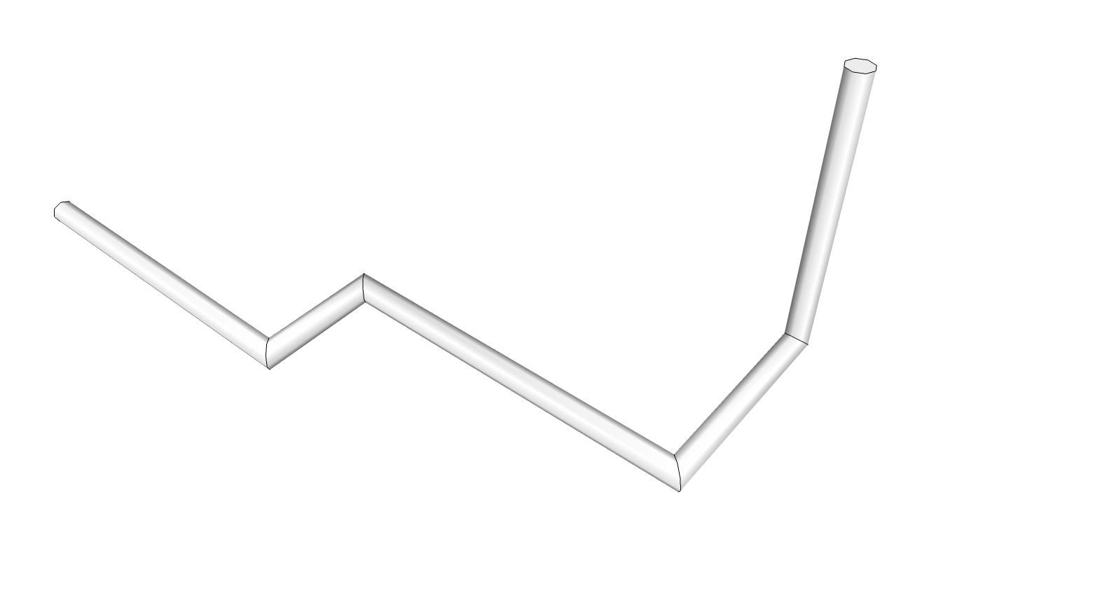
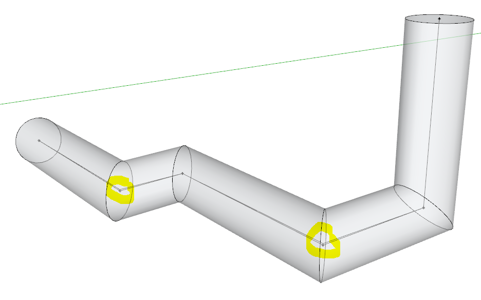
I noticed that some of the lines forming the path were not quite horizontal...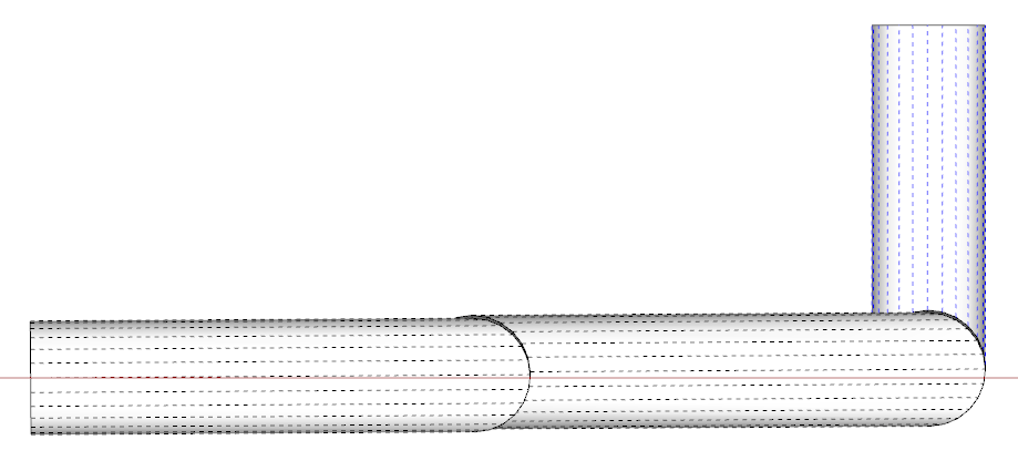 If the pipe's extrusion diameter is at a certain threshold then the coded FollowMe fails, I suspect its something to do with tolerances as the pipe twists around the form the side's segments can't intersect and form the pipe-run.
See the screen-grab when I use it on two individual pieces successfully...
Hidden Geometry ON, exploded and intersected. If I 'flatten' the slightly sloping lines it will 'PipeAlongPath' just fine [front one].
 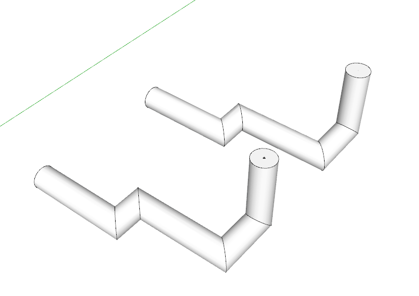 If I copy the top-most circle from that one and paste it onto the original path [or simply draw a flat circle on the top-end of the path] [the back-one], then select the path and use the native FollowMe on that circular face it will make the pipe with the slightly sloping sections...
 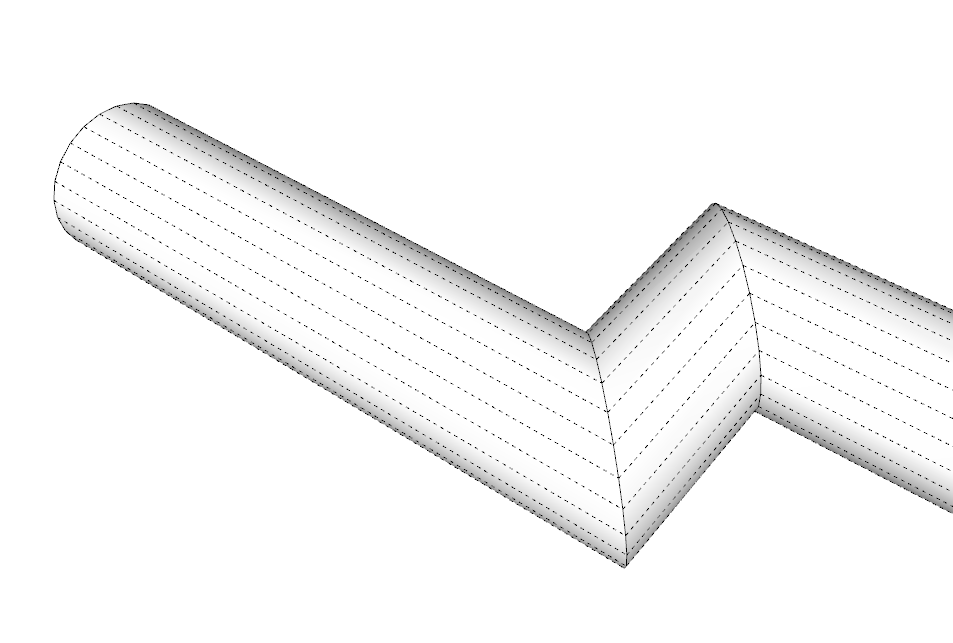 Because the slight slopes of the paths and the diameter threshold are not obviously linked I can't see how to trap it consistently.
I tried introducing a vector check on a pipe sections of multiple part pipes, and if that piece of pipe is within a limit of being coplanar with the next section etc, then it was made as if it were coplanar [the vertices are slightly adjusted in the Z]... But it's clunky and awkward... This example in Xray shows that some of the verties in the paths have to be adjusted by ~1" to get PipeAlongPath to make the extrusion with the coded-followme, but the native-FollowMe works OK without that tweak - it's plain weird 
 Comments appreciated - I'll hold off issuing any updates until someone responds...
-
Interesting. I see the issue but it did work for me. I wonder how the path got drawn with those very small errors.
-
It works for me too, at say 4" or 6" diamter, but when I go up to ~40" if freezes as the coded-followme gets stuck in an unbreakable loop, trying to decide how to proceed around the slight twist!!
The native-FollowMe succeeds using the same geometry... BUT one might reasonably supposed that both of the methods used very similar algorithms!
Unfortunately there is no 'direct access': in code it's simplyface.followme(edges)- which works 99/9% of the time, until someone contrives a combo of very slightly skewed paths that trips it up...Sometimes pipes do need a slight fall to 'drain' etc.
But this is <0.375 degrees - aka 'flat'.
So if I force it 'flat' in parts as I've indicated, then it works...
BUT I don't want to make the pipe's path subtly different from the user's selected edges, unless I really need to... -
Please do not fret about the rare freezes. Kindly work on the default input box stuff mentioned above - if you so feel inclined. Speaking of 'inclined' - yes this particular pipe run is sloped for drainage. Even with such runs the plugin rarely freezes and Mr.TIG deserves accolades.
-
Construction points are appearing when I explode a pipe-along-path group. This only seems to be happening recently - maybe after I updated to the latest version? If it was engineered into the script, I am interested to know the purpose. I can't delete them by "edit>delete guides" because guides that I have set up permanently in my model will disappear - regardless of being in a locked group. And selecting and erasing each guide point is time consuming.
-
@pipingguy said:
I can't delete them by "edit>delete guides" because guides that I have set up permanently in my model will disappear - regardless of being in a locked group. And selecting and erasing each guide point is time consuming.
You can use Thomthoms selection tools to select all guide points in a group and delete them in one step.
-
Why not just opt for no C points when you make the pipe?
I can see that some folks could use those C points as data points for locating the pipe in space. You could export their coordinates to a spreadsheet, for example, and manipulate them.
Why are you using guidelines as "permanent" features in your model? They weren't intended for that.
-
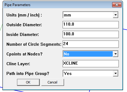
The Cpoints are optional.
Answer 'No' to stop them being added during that session.
Their function is to allow snapping at nodes etc.
If you want to edit the script with Notepad++, so the default is 'No' find the line reading:
@cpoints = "Yes"
and change it to
@cpoints = "No"
You can also change other defaults - for example if you always want 12 segments... -
I thought I had the latest version which I downloaded from the rhin.crai.archi site. (if said site is obsolete, why does it still exist?) Then I accessed TIG via the the author pull-down menu in sketchucation's plugin store and did not see 'pipe-along-path' listed. (I was not provided with the option to scroll to a next page). Then I used the plugin store's search feature and found it. So now that I am up to date, I would suggest giving the users a way to change the input box default to suit their typical work habits. With me, it's always inches and the inside diameter is always zero.
-
You didn't read TIG's last post? He gave you a way to change the default settings.
If you're always going to want a zero inside diameter and no C points, you could use Tube Along Path instead.
-
Or Didier's Lines2Tubes which is available from the plugin store.
http://sketchucation.com/forums/viewtopic.php?p=88592#p88592 -
@pipingguy said:
Then I accessed TIG via the the author pull-down menu in sketchucation's plugin store and did not see 'pipe-along-path' listed. (I was not provided with the option to scroll to a next page).
You have to change from "recent" to "full list" to see all the plugins from one author...
-
column lines - xlines - guides.skp
As to Dave R's question, "Why are you using guidelines as "permanent" features in your model? They weren't intended for that." In AutoCAD I create XLINEs and place them in a locked and faded layer and assign them a specific color. This now establishes a secure column line grid upon which the rest of the model is measured and coordinated from. I suppose I could create a grid using intersecting lines in sketchup, erase the resulting faces, and put them in a locked group. But they would blend into the remaining myriad of lines. At least with construction lines, they are dashed so they don't stand out to much, yet are quickly recognizable. (see attached SU partial model) Perhaps you can tell me of a popular plugin that generates dashed lines? BTW - what does 'place inline' mean in the reply editor regarding the attachment of a file? -
Sorry. OK - I will look at the script with notepad. But I literally have not dealt with any kind of of computer code since an introductory course into Fortran or whatever it was back in the early seventies. something about flowcharts / if yes, then / if false then....blah blah. And then we put the code into an IBM punchcard machine. (junior high school) LOL!!!!
Hello! It looks like you're interested in this conversation, but you don't have an account yet.
Getting fed up of having to scroll through the same posts each visit? When you register for an account, you'll always come back to exactly where you were before, and choose to be notified of new replies (either via email, or push notification). You'll also be able to save bookmarks and upvote posts to show your appreciation to other community members.
With your input, this post could be even better 💗
Register Login


Advertisement