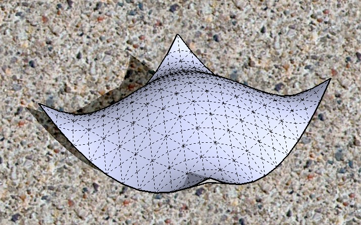
[Plugin] SketchyFFD (Classic)
-
I would name my next child SketchyFFD if we could make the edge curves (borders) static or locked.
Any possibility this could be worked out?
Danke,
Brad

-
 that's funny.
and YES... this would be VERY COOL INDEED.
-
@greentoaster said:
I would name my next child SketchyFFD if we could make the edge curves (borders) static or locked.
Indeed, that would be great as that would allow making a FFD group of parts of the organic shape . Manipulating that part would hold a seamless transition with the rest of the object.
-
So i'm using SketchyFFD on a surface I created with SoapSkin Bubble.
It works, however the FFD nodes are not aligned in the group that the surface is drawn. They are created next to the surface. So when I'm editing the nodes, I can't really tell which one is relative to which part of the surface.
Why are my nodes not aligned with my group when they are created?
Am I doing something wrong?
Dave.
-
Try exploding and regrouping the geometry. The FFD script wants the geometry positioned in a certain way inside the group.
@davecoopstl said:
So i'm using SketchyFFD on a surface I created with SoapSkin Bubble.
It works, however the FFD nodes are not aligned in the group that the surface is drawn. They are created next to the surface. So when I'm editing the nodes, I can't really tell which one is relative to which part of the surface.
Why are my nodes not aligned with my group when they are created?
Am I doing something wrong?
Dave.
-
CP - Thanks! That worked like a charm.
I do think it would be easier to control if the nodes were directly ON the surfaces that you are trying to deform. So you knew EXACTLY what part of the surface the node controlled.
At least they are in a relative position, now that I've exploded and re-grouped.
Dave.
-
@davecoopstl said:
CP - Thanks! That worked like a charm.
I do think it would be easier to control if the nodes were directly ON the surfaces that you are trying to deform. So you knew EXACTLY what part of the surface the node controlled.
At least they are in a relative position, now that I've exploded and re-grouped.
Dave.
The math is such that the control points need to be created exactly on a 3d grid.

-
I posted a new version with a few minor changes.
Update Mar 21.
-Moved all FFD right click menu items to a sub menu.
-Fixed a bug that forced you to have a least 2 control point in each direction. You can now have do 2D grids. IE. 1x4x3.
-Added an option to create a NxN 2d patch. A grid with a control point at each intersection.Get it here:
http://www.sketchucation.com/forums/scf/download/file.php?id=6745 -
thank you Chris! the 2D grid ability is Key!
-
@cphillips said:
-Added an option to create a NxN 2d patch. A grid with a control point at each intersection.
I mis-read this at first -- I thought you were saying you made it possible to encase the model in a grid box, rather than floating points (to help visualize the distances between points).
Great work over all! I'd love to see SU incorporate this as a scale tool (lattice) option.
--alz
-
@unknownuser said:
-Added an option to create a NxN 2d patch. A grid with a control point at each intersection.
BEAUTIFUL!!! THANK YOU!!!

-
I am having trouble with the new FFD.
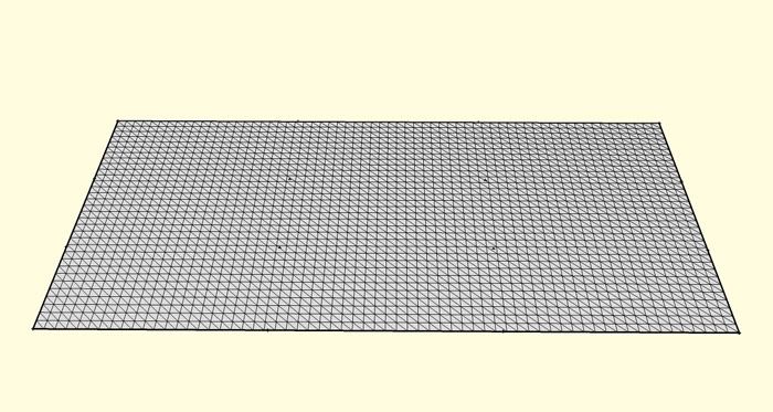
I made a so called 'TIN', made a 4,4,4 FFD out of it and wanted to let the surface curve upwards so I selected the points of the short outer edge and moved them up.
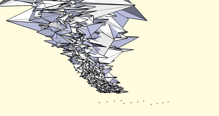
The FFD result however is a mesh soup....
before:

after:

-
Hey, that's very cool . . .
-
Looks kinda like a tornado to me.not quite what you were aiming for?

-
Hrmmm. Not sure why that would fail. Could you post the model?
Also. Try a 4,4,1 FFD for that mesh.
@kwistenbiebel said:
I am having trouble with the new FFD.
I made a so called 'TIN', made a 4,4,4 FFD out of it and wanted to let the surface curve upwards so I selected the points of the short outer edge and moved them up.
The FFD result however is a mesh soup....
before:

after:

-
How does the "make Patch" work ?
When I use the default setting a get a mesh that is 762mm x 762mm. What do I do when I want it to be 20000mm x 20000mm ?
-
@jorgensen said:
How does the "make Patch" work ?
When I use the default setting a get a mesh that is 762mm x 762mm. What do I do when I want it to be 20000mm x 20000mm ?
Its number of cells in either direction and the width and height for each cell. I figured it would use whatever units were set but it doesn't sound like that is the case. Its probably in inches.
-
I just wanted to say that your script is greaaaaaaaat Chris! Really! I was actually looking for something like this.
I was messing around trying to model an airplane, and I was trying to make the front end of the body wider, but I couldn't do it with the sketchup scale tool. I kept googling for "sketchup distort tool plugin" with no success, till I remembered coming across this thread before, so I looked for it, downloaded the script, and it WORKS LIKE A CHARM! Really great!
They should really be adding this to the functionality of the scale tool in sketchup 7. Like with a modifier key or something. You know, something like: "Alt to distort" or something like that.
-
@justry said:
I just wanted to say that your script is greaaaaaaaat Chris! Really! I was actually looking for something like this.
I was messing around trying to model an airplane, and I was trying to make the front end of the body wider, but I couldn't do it with the sketchup scale tool. I kept googling for "sketchup distort tool plugin" with no success, till I remembered coming across this thread before, so I looked for it, downloaded the script, and it WORKS LIKE A CHARM! Really great!
They should really be adding this to the functionality of the scale tool in sketchup 7. Like with a modifier key or something. You know, something like: "Alt to distort" or something like that.
Thanks Justry!
Could you post a picture of your plane?
Chris
-
Well, it's still not finished, but if it looks good when I'm done (hopefully!) I'll post it!
Advertisement


