How is this possible? Please help.
-
We all know what happens if you have lines that are almost on axis, but not quite. I took this component out of a model for you all to look at. This seems like a paradox: 10 of 12 lines of a box are on axis. The lines are all of equal length.
Have I just been looking at this for too long? Is the answer sitting in plain view?
PLEASE, THIS IS DRIVING ME CRAZY!!
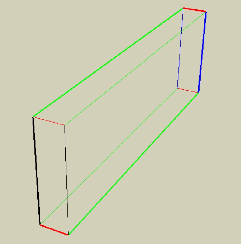
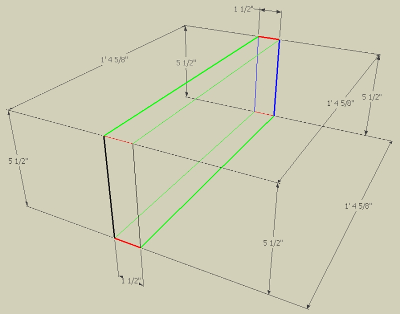
-
thats really strange i dont quite get it, could it be possible that the measurement of the line is off by like 0.0001 of a millimeter or something?
-
well the box was made with push/pull so its unlikely. If it were off by a little it should say something like ~5 1/2". Plus the model is shown in wire frame with color by axis on. When you turn on faces all the faces appear.
If you purge the model and check for errors it is fine. When you look at the geometry there are 12 lines and 6 faces so there are no little lines throwing things off.
Its really wierd. Thanks for looking at it.
-
Sketchy,
I have experienced this before,and one way to find the culprit is to draw new lines on Axis....and measure from them to double check things.
In your case I drew lines on axis from the midpoint of the component,and measured to the corners.
Well the end of the component that is not displying the axis colors properly is in fact off the blue axis...........very little,but off.BTW, I don't know how it happens...just does sometimes.
Charlie
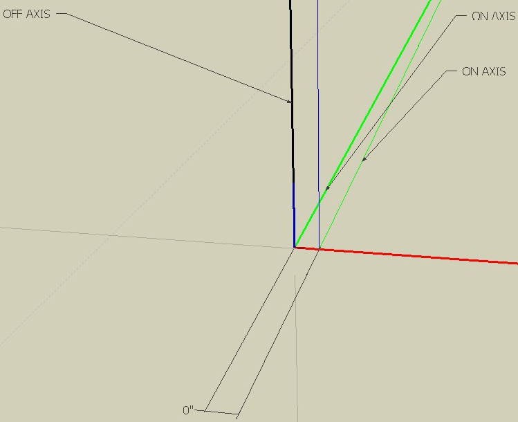
-
I've no idea how it happened but if you zoom right in on the corner you can see that it is off vertical.
Bob
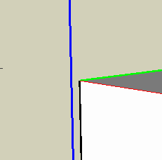
-
I think that this is easier to "accomplish" when your model has a lot of geometry already there. Also, trying to model too quickly "helps". It must be the inference engine doing some odd things under stress. I think that it happens more often with the pushpull tool than if you model slowly using the line tool.
Anssi
-
Thanks for the help GreyHead. I think you have successfully proved that the line is off axis but there is something that still troubles me:
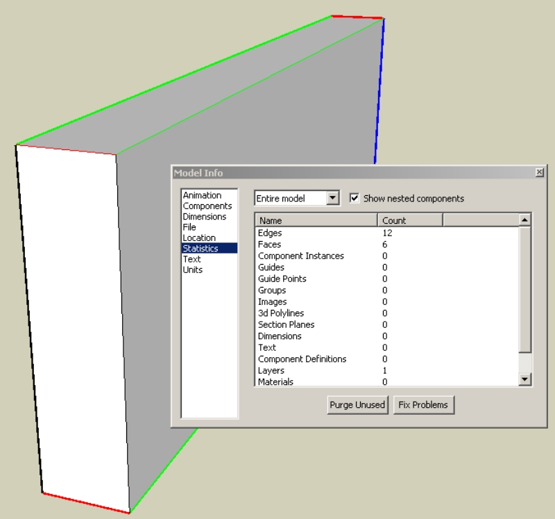
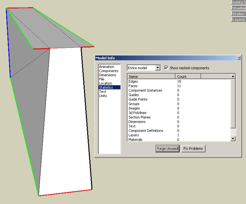
How is it possible to have a box with 10 lines on axis (90 deg from eachother) and 2 lines that are off but have only 6 faces that connect them?
The first pic shows the faulty box and its statistics. The second is an exaggerated box that has 10 "on-axis" lines and 2 off. You can see that this needs more lines and faces to close the shape.
And Anssi yes the model this came out of is pretty big (over 300,000 faces).
-
Hi,
The error is tiny. My guess FWIW is that you hit a rounding limit somewhere and something went to +1 pixel or +.00001mm instead of zero. As you say if the error wasn't lost in the noise then it wouldn't be possible.
Bob
-
that must be it GreyHead. The color by axis feature must be a hair more accurate than the line and face engine.
-
It's easy enough to get 10 lines parallel and perpendicular, but have two off. See the exaggerated picture below.
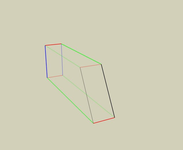
But I don't think there's any "rational" explanation to what happened to you. It's happened to me a couple of times and after I've figured it out, trying to fix it is impossible. The only thing is to start fresh.I think it's probably a matter of how math is done in the SketchUp engine. Inside computers, sometimes 2+2 = 3.99999999999999999999999999999 instead of 4. I run into problems like this more frequently when I've got a planer outline which won't make a face. Breaking it down into subparts, then deleting those lines makes the face appear like it should have.
-
sketchy,
I see that SchreiberBike “beat” me as far as the remark about the
exaggeration in the green direction instead of red. It is quite possible to have only two black edges in the box.
But here is another thing. Note that ALL your dimensions are non-associated.
i.e. they don’t represent the actual line lengths.
I do agree that this box is a little monster and I have never experienced this odd behaviour working with SU.
I will have a closer look and let you know if I find some explanationcheers,
Wo3Dan -
Ah good one SchreiberBike, I was just staring at it for too long I suppose. So it does seem like a rounding error after all.
Its so good to have this forum, you all keep me sane (somewhat).
Thanks guys -
sketchy,
Could you please tell us whether the box or the face that you pulled up was originally created in SU? Or was it imported from another application?
The non-associated dimensions (even though not text for they change by changing the units format) puzzled me too but I realize that this can easily be done with {copy component, then delete component in model, then paste (component) in place}.All the components edges are off axis but 10 out of 12 are just within the tolerance zone to look on axis.
All the faces show how they leave this tolerance zone when you pull them out just a little bit. The black ones will get within this zone once you just push the top face down.
The four vertices of the ground plane are not even coplanar. Strangely enough the connecting edges still 'support' a face.I strongly suspect that the original box or its ground plane is from an imported non-SU model.
My faith in SU is still there! -
Wo3Dan
So I realize how the dimension lines became non-associated. I took the component out of my model and put in a skippy of its own so it would be small enough to share. I made some dimensions and then grouped them so I could hide them all at once. This must break their association.As far as its origin, it was definitely made in SU 6 Pro (latest patch). There are a few pieces of furniture in my model that are from the warehouse but this block was made in the walls, well away from any furniture. All the groups that had this error were native to SU. I will double check the source of my windows, I think I made them.
I had a bunch of components that had this problem. However I bet the problem had one single origin. Since the components were all framing members for window openings in a strawbale wall I would use one as a reference for the next. So if the first one had an error it would be replicated over and over again.
Thanks for looking at it.
-
the windows were modified versions of a window from the component library.
-
Was the original done far away from the origin?
-
I'm assuming you mean the original box that has the error.
Not too far, but the origin has moved a couple of times. It's a large model with topo terrain and many lines and faces (hundreds of thousands). I could give you a more specific distance if you think it would help.
-
So,?
Is there no interest to my earlier post where I clearly show 2 converging lines on the green axis contributing to the vertical lines off the blue axis(black).Ck the posted SU model....cause I'm just saying.
Best,
Charlie -
There was another thread on this problem quite a while back, SU5-ish. Push/Pull was involved. The problem child was located far from the origin. There also could have been an axis change somewhere along the line. Both things seemed to be involved.
He sent his problem file with everything deleted and purged except the cube with extruded cut-outs. Several people tried working on that file. Simple Push/Pull shapes done in his file would not stay square for us. It was weird.
-
Charlie, I did check your model when you posted it and sorry for not acknowledging it then. I appreciate your effort in this.
As you and GreyHead discovered there are some lines in the model that are very slightly off. I'm now trying to figure out how this originated, but I'm not sure its possible to determine this.
Gata- thats a pretty interesting case and sounds somewhat similar. But since the moral of that story is also that sometimes SU gets thrown off a little I guess I'm just going to keep checking my color by axis view every now and again.
Advertisement


