Any good tutorials on BEVEL gear design in SU?
-
Did you try SPGears?
Download the free D'oh Book for SketchUp 📖
-
As Rich suggests, SPGears is a good option. If you can use standard bevel gears you might check manufacturers and suppliers for files you can use in SketchUp. For example I got a STEP file for the gear shown here from McMaster-Carr which I imported into SketchUp using the Universal Importer available in the ExtensionStore. The result can easily be modified for the shaft it needs to fit and so on.
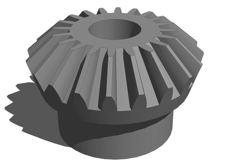
Since you are modeling for 3D printing, do the modeling in meters to avoid issues with tiny faces.
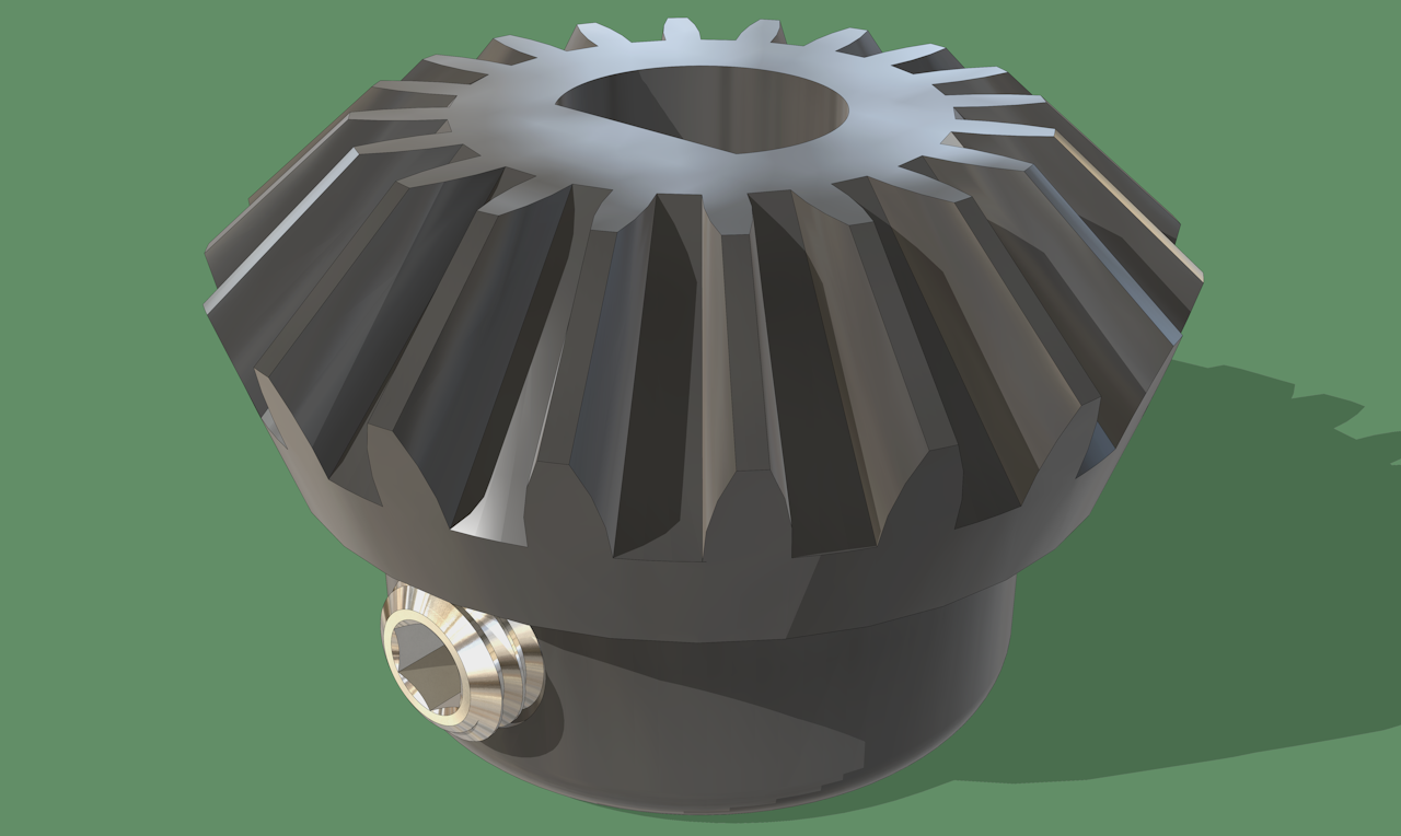
Couldn't help but do a little playing while avoiding work I should do.
Etaoin Shrdlu
%
(THERE'S NO PLACE LIKE)
G28 X0.0 Y0.0 Z0.0
M30
%
-
@Rich-O-Brien
Thanks. Not sure that will work for me in SU 2015. Info says the gears are mainly for SP and may not be OK if 3D printed.
But I will try it later this week.jgb
jgb
-
@Dave-R
Thanks, but nearly nothing I design has a standard base that I can use. Believe me, I looked.jgb
-
@jgb said in Any good tutorials on BEVEL gear design in SU?:
Info says the gears are mainly for SP and may not be OK if 3D printed.
You can certainly modify the geometry output of SP Gears to make solids suitable for 3D printing.
You could also modify standard gears like the one I showed to make any custom sized gears.
-
@Dave-R
I'll give it a try.
Thanks -
FWIW, here's what it takes to make a solid object from a gear created by SP Gears.
-
Thanks. It loaded OK, and I made test gears OK. Makes nice looking gears.
I figured out how to reduce the lines count and make it solid.But now I need to make gears to very specific sizes and my foggy brain cannot interpret the dialog box to do it beyond a simple diameter and tooth count.
Also, it produces gears that will be difficult to print; too many overhangs equates to a lot of tiny supports to be removed, and many line lengths are smaller than the printers print resolution. The gears in your diagrams above are far closer to what I need, but I can tweak the SPGears output for that, given each tooth is a component.
Quite frankly, I do not fully understand gear design, beyond number of teeth, diameter (pitch radius), face width and bevel angle.
I really need some tutorial in understanding the SPGears dialog box, and what "Diametral = xx" means.
I have basically 2 types of 90 degree straight bevel gears to make. One pair of same everything; 25mm diameter 24 teeth (simple) and two sets where the diameter ratios are 50mm:280mm and 50mm:140mm. Those are the hard ones to get properly meshed teeth with SPGears.
I can probably play around to get them to work once I understand SPGears dialog box.
Can you help me with that? -
This diagram comes from https://www.engineersedge.com/gear_formula.htm Take a look at that site to see how all the numbers are calclated.
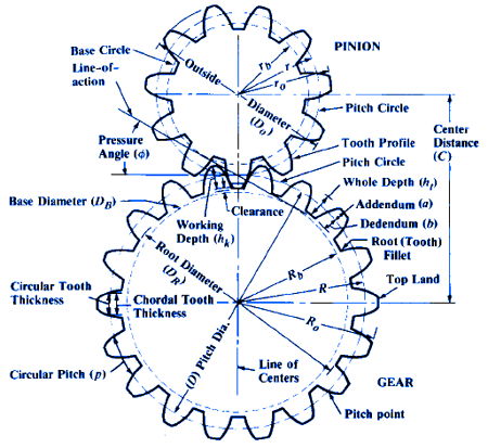
Also see the information at https://www.engineersedge.com/gear_menu.shtml
There are gear generator tools there where you can put in the numbers you want and it'll calculate the rest.
@jgb said in Any good tutorials on BEVEL gear design in SU?:
But now I need to make gears to very specific sizes and my foggy brain cannot interpret the dialog box to do it beyond a simple diameter and tooth count.
When you refer to diameter are you talking Outside Diameter (O.D.) or Pitch Diameter (D)?
@jgb said in Any good tutorials on BEVEL gear design in SU?:
it produces gears that will be difficult to print; too many overhangs equates to a lot of tiny supports to be removed
Where are you getting these overhangs? Maybe you just need to invert the object. I expect you're going to have to live with some overhangs somewhere.
@jgb said in Any good tutorials on BEVEL gear design in SU?:
many line lengths are smaller than the printers print resolution.
Are you doing your modeling in millimeters? As I wrote before, do the modeling in meters. That is, treat millimeters as meters. So your 25mm gear would be 25 meters. When you export the .stl with model units set to meters, and them import the .stl into your slicer in millimeters, the gear will be the right size. For example, here's the SketchUp model of the gear I showed.
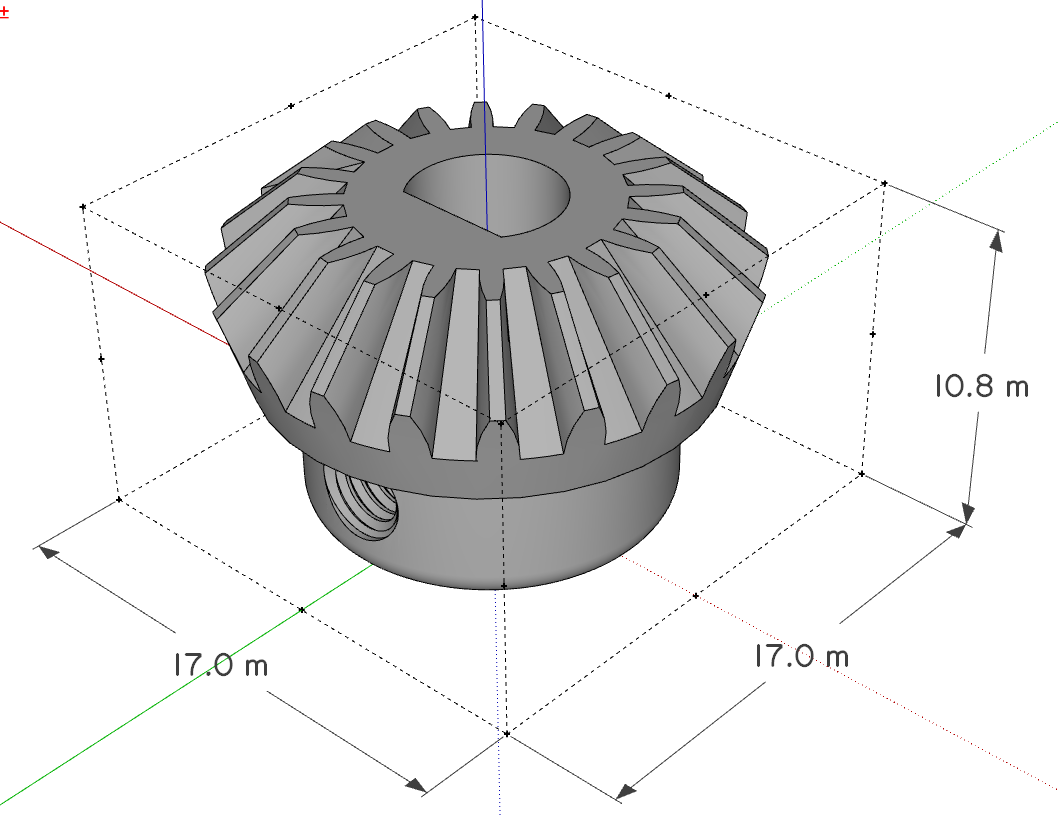
And the resulting .stl in the slicer. Same dimension numbers but in millimeters, not meters.
@jgb said in Any good tutorials on BEVEL gear design in SU?:
and two sets where the diameter ratios are 50mm:280mm and 50mm:140mm. Those are the hard ones to get properly meshed teeth with SPGears.
I don't think that's specific to the extension. Look at standard gear charts. You'll see that there are only certain combinations that work together.
Is it really the gear diamter that is important? Normally the gear ratio would specify the number of teeth. 50:280 as a gear ratio would also be 1:5.6 so you could start with some number of teeth for the small gear and multiply it by 5.6 to get the number of teeth for the large gear. The actual diameters of the gears may not be exactly 50mm and 280mm
-
Another thing to keep in mind is that the bevel angle on the gears may not be 45° for a right angle drive. You'll have to play with that to get the correct angles so the teeth will mesh properly. You may not be able to get the exact ratio you're after, either.
See the calculator on this page: https://www.engineersedge.com/calculators/spur_gear_calculator_and_generator_15506.htm for figuring out pitch diamter based on the number of teeth.
-
Thanks for the reply.
I will be open (to a limited extent) about the model I need to build. Can't show all due to patent reasons.
I am using a Centimetre Drawing unit which will translate to Millimetres when printed on a Snapmaker A350 (when I get it).
It has a print resolution of .05mm in XY and .12mm in Z axis. So my minimum line segment length has to be .05mm or greater.
So drawing in Centimetres or Meters makes little difference, except I can mentally visualize in Centimetres better.The actual dimensions of the gears are determined by several factors, but can vary a bit (1 or 2 mm) if and as needed. However the ratios are firm.
All are bevel gears, ranging in size from (about) 20mm (printed), 25mm, 50mm, 140mm and 280mm (see drawing). I usually go by outside diameter rather than pitch diameter, but I can adjust to one or the other if needed.
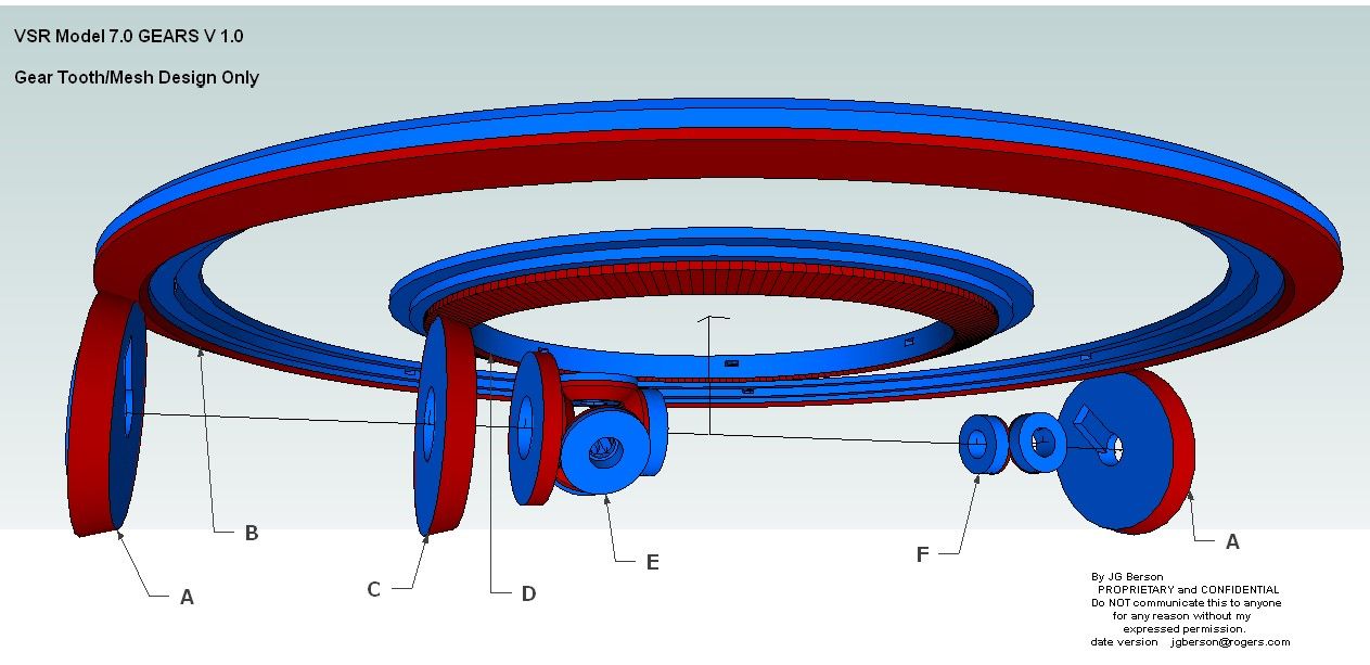
There are 6 types of gears, A to F.
A - About 50 mm diam printed. There are several of these same gears, but I only show 2. The tooth count really does not matter and I will adjust as needed.
B - The Main ring gear is about 280 mm diam meshing to gear A. Again, tooth count really does not matter but MUST be an even count.
C - MUST be the same diameter and tooth count as A, but the bevel angle is different. There is only 1 in the model.
D - Is a smaller ring gear meshed only to gear C. The diameter and tooth count MUST be EXACTLY 1/2 that of gear B. (140 mm diameter) This is critical.
E - Is a "standard" 45 degree bevel gear, about 25 mm diameter and no specific tooth count, but not too fine. There are 5 of these same gears forming a differential.*Ignore the unlabelled gear to its left. That is a whole other problem to solve. It is a worm gear with diam and tooth count to be determined by some complex math once these other gears are known as well as other factors.*F - Are also 45 deg bevel gears, same as gear E but smaller, about 20 mm diameter. There are 6 in the model.
So the 2 really difficult gears to design are gears B and D in order to mesh properly with gears A and C respectfully..
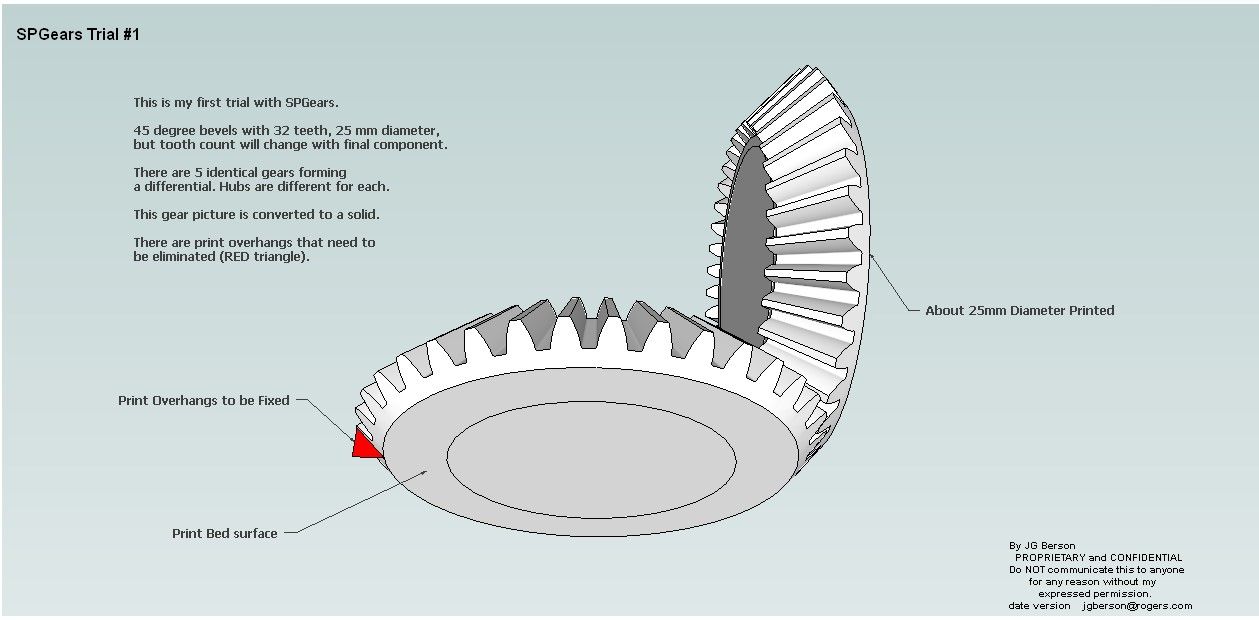
FYI; Gears A, C and E are connected with concentric shafts and form the 50% RPM reduction needed between gear A and C.When I first started SPGears, I created a 45 deg bevel gear with some arbitrary values, as I still do not full understand its dialog box.
I played around a bit to figure what it was made of; (lots of components) then simplified it to a solid and removed unnecessary soft lines.
But it also produced gear teeth with lots of tiny overhangs (in red) where a lot of work will be necessary to remove support material. I will modify the single gear tooth component to eliminate that overhang.
I would appreciate if you could fully explain the SPGears dialog box as some of the terms are not reflected in other documentation.
jgb
-
@jgb Hi, first of all, congratulations. At your age, you still have a strong desire to create. I am retired and 100% disabled, and I still want to create something. If you want, I can give you a hand, but you have to show me with a rough drawing without gears what you want to do. At most, you can make the gears without the teeth. Then, if you want and without any obligation, I can help you; I have plenty of time.
-
@jgb If instead you want to look for something already done, try checking this site which is free and has many models, but they are mostly in STEP or 3DSMax format. Then I can explain to you how to convert 3DSMax files for free and legally."If you want to look for something already done, try checking this site that is free and has many models, but they are mainly in STEP or 3DSMax format. Then I can explain how to convert 3DSMax files for free and legally.
-
@alexpacio2013
Thanks, but there is nothing about my model that has predefined printed parts. Other than motors, screws, bearings and some electrical parts, all of it is a unique design.
I have visited this site before and it has a lot of neat stuff, but nothing appropriate to my model. -
@alexpacio2013
Thanks. I know what you mean to be retired and have "plenty" of time on your hands. Even so, I have been working on this concept for over 7 years and the model to prove it will work for about 4 years now. Plenty of time but plenty of distractions as well.My model design is complete, except for the actual gears design and some final wire routing.
However, if you have expertise in trigonometry and Excel I could use some help in some spreadsheets I cannot wrap my head around.
The main spreadsheet is a simulation of the model both for proof of concept, animated demonstration/presentation and design of some part sizes for a real life-sized device.I would need you to commit to an NDA to bring you on board, as I have about 7 patents to reveal for you to help me..
-
I have no problem signing an NDA; it’s not that I’m an engineer or an expert in complex calculations. I have some experience and wherever I can, I help you, especially with the drawing, so don’t worry. If you can tell me which sector the idea is in, maybe it has been one of my experiences. My email is [Redacted]@gmail.com.
-
@jgb said in Any good tutorials on BEVEL gear design in SU?:
I would appreciate if you could fully explain the SPGears dialog box as some of the terms are not reflected in other documentation.
Looks like Roberto is taking over so I'll leave it to him.
-
@alexpacio2013 I removed your email address. Last thing you need to tons of Spam.
If you guys need to swap details use the Chat feature to privately discuss options.

-
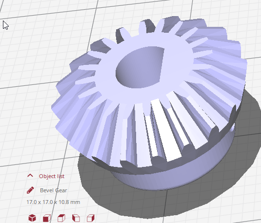
Spent the better part of yesterday getting this gear right (I hope). It is a 24 tooth bevel gear 22.5 mm diam (drawn in centimetres). Gear E in my diagram above.
SPGears created a fairly close model. I had to compare that model to my desired cross section and manipulate it into shape.
I had to get rid of the overhangs on each tooth to avoid any supports. That was the tedious part. (I'll show how later today)Thankfully SPGears creates each tooth as a circular array of one tooth, so editing is relatively easy.
Then I had to make a single generic hub as the 5 gears, plus the other smaller gear (scaled down a bit) have different hubs. That part was far easier.
An SPGear is actually a group of 2 nested groups, the set of teeth, and the hub, done in a strange way, but hey, it works. I made it a component of the 2 nested groups.
To make sure the gears mesh correctly (fingers crossed) I duplicated the SPGear and turned it 90 deg. I drew an axial line to the vertex within the component for alignment purposes. I then turned it 90 degrees and mated them at the vertex. I also rotated the vertical gear 7.5 deg (24 teeth) to properly mesh the 2 gears. That resulted in a large gap between teeth.
By eye I moved the vertical gear along blue and red axis (equally) till I got a nice mesh with a bit of play. Then adjusted (shortened) the vertex end of the axial line accordingly.
There were tiny overlaps.
So I had to scale the 2 face ends of the teeth a bit to clean up the mesh. Only after all that was I able to redraw the large end to eliminate the overhangs.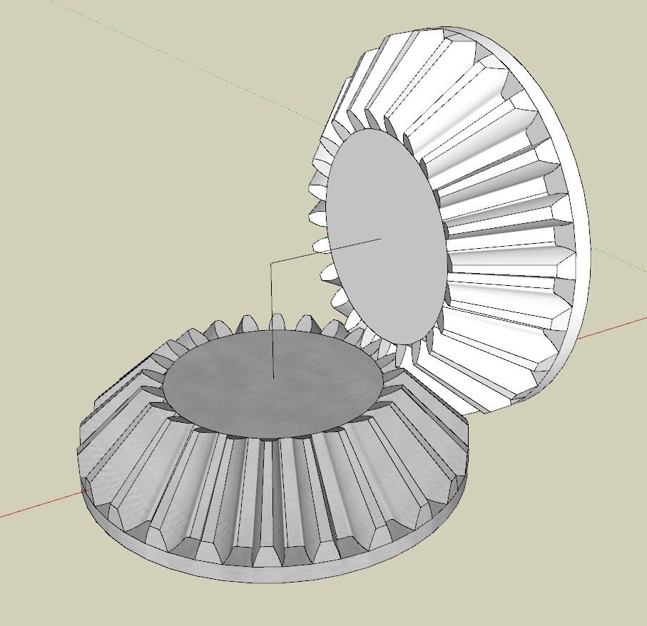
I cannot yet print a pair to test as I do not yet have a printer (long story, and it's not the $$$)
Later.......
Hello! It looks like you're interested in this conversation, but you don't have an account yet.
Getting fed up of having to scroll through the same posts each visit? When you register for an account, you'll always come back to exactly where you were before, and choose to be notified of new replies (either via email, or push notification). You'll also be able to save bookmarks and upvote posts to show your appreciation to other community members.
With your input, this post could be even better 💗
Register Login


Advertisement