sketchucation logo sketchucation
    • Login
    Oops, your profile's looking a bit empty! To help us tailor your experience, please fill in key details like your SketchUp version, skill level, operating system, and more. Update and save your info on your profile page today!
    🛣️ Road Profile Builder | Generate roads, curbs and pavements easily Download

    Intersect function

    Scheduled Pinned Locked Moved SketchUp Discussions
    sketchup
    14 Posts 4 Posters 1.6k Views 4 Watching
    Loading More Posts
    • Oldest to Newest
    • Newest to Oldest
    • Most Votes
    Reply
    • Reply as topic
    Log in to reply
    This topic has been deleted. Only users with topic management privileges can see it.
    • TIGT Offline
      TIG Moderator
      last edited by

      The file you attached is the backup file ["step test 15.6~.skp"]
      Note that on a PC it'd be named "step test 15.6.skb"

      That said, and assuming that the SKP's contents are much like the main model...

      There are some critical areas that need fixing.
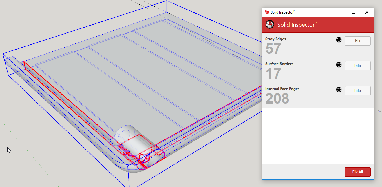
      Try thomthom's SolidInspector² to see them...
      It is a relatively simple form that can be made from scratch quite easily, but in its current 'mangled' state it'll be quite hard to 'fix'...

      TIG

      1 Reply Last reply Reply Quote 0
      • L Offline
        Leggy
        last edited by

        sorry try again


        step test 17~.skp

        1 Reply Last reply Reply Quote 0
        • L Offline
          Leggy
          last edited by

          sorry correct one


          step test 15.6~~.skp

          1 Reply Last reply Reply Quote 0
          • TIGT Offline
            TIG Moderator
            last edited by

            That's the backup of a backup file ! ending in "~~.skp"
            Don't you have a file named "step test 15.6.skp" ??
            With not ending ~ characters - which show it's a backup file ?
            If you have worked on the backup file you should rename the file without the ~ otherwise it's the route to confusion......

            TIG

            1 Reply Last reply Reply Quote 0
            • L Offline
              Leggy
              last edited by

              try again


              step test 15.6.skp

              1 Reply Last reply Reply Quote 0
              • L Offline
                Leggy
                last edited by

                morning
                how can you tell what's mangled 😮 , I keep getting messages that something is wrong , but can never see why
                thanks

                1 Reply Last reply Reply Quote 0
                • Dave RD Offline
                  Dave R
                  last edited by

                  There's a lot of bad geometry created by the intersection of the two shapes and you need to clean it up. Some of it Solid Solver or Solid Inspector will do but a lot of it will need to be done manually.
                  Screenshot - 7_5_2019 , 7_20_55 AM.png

                  Hiding outer surfaces will make it easier to get inside and erase the unneeded stuff.

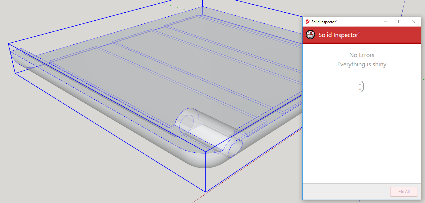
                  When you get it all unmangled, it should look like this.
                  Screenshot - 7_5_2019 , 7_21_20 AM.png

                  Much of the problem comes from the size you are working at. If you'd taken the advice given in your other thread about working at a larger scale, you would have an easier time of it.

                  Etaoin Shrdlu

                  %

                  (THERE'S NO PLACE LIKE)

                  G28 X0.0 Y0.0 Z0.0

                  M30

                  %

                  1 Reply Last reply Reply Quote 0
                  • TIGT Offline
                    TIG Moderator
                    last edited by

                    As Dave says...
                    It's not a solid because it has lots of modeling errors.
                    SolidInspector² shows you have many internal partitions and missing faces - both of which prevent solidity - every edge must support two faces - no more, no less.
                    There are also a lot of leftover faces and edges within the form [especially near the part with the hole].
                    Your form's size also gets very near the 1/1000" tolerance limit - especially where the curved upstand's segmentation doesn't match the part around the hole and the 'valley' between them is therefore not evenly formed.
                    Modeling with softened/hidden edges also makes life difficult to see what you are doing.
                    In the attached SKP [v2017] I've fixed the issues and it's now reporting as a solid.
                    Note how I've tweaked the Style to shown end-points and profiles, so the repairs are then easier to see.
                    To get inside I used section-cuts [fill off in Style].
                    I also un-smoothed all edges, and selected all to use 'unhide', so I could see everything as I went through erasing unwanted geometry.


                    step test 15.6.skp

                    TIG

                    1 Reply Last reply Reply Quote 0
                    • pbacotP Offline
                      pbacot
                      last edited by

                      You guys have a lot of patience and generosity...

                      MacOSX MojaveSketchUp Pro v19 Twilight v2 Thea v3 PowerCADD

                      1 Reply Last reply Reply Quote 0
                      • L Offline
                        Leggy
                        last edited by

                        you guys certainly do , Thanks so much for your help
                        I did scale it up by x10 but obviously wasn't enough
                        ill download the extensions next week
                        Thanks again Dean

                        1 Reply Last reply Reply Quote 0
                        • L Offline
                          Leggy
                          last edited by

                          so is that view on x-ray?

                          1 Reply Last reply Reply Quote 0
                          • Dave RD Offline
                            Dave R
                            last edited by

                            @leggy said:

                            I did scale it up by x10 but obviously wasn't enough

                            As I wrote the other day in your other thread:
                            @unknownuser said:

                            you should model in meters instead of millimeters.

                            That's effectively scaling up by a factor of 1000! I don't know why people are so afraid to scale the model up sufficiently.

                            @leggy said:

                            so is that view on x-ray?

                            Yes.

                            Etaoin Shrdlu

                            %

                            (THERE'S NO PLACE LIKE)

                            G28 X0.0 Y0.0 Z0.0

                            M30

                            %

                            1 Reply Last reply Reply Quote 0
                            • L Offline
                              Leggy
                              last edited by

                              Hi
                              I see now its in solid inspector, I've downloaded
                              thanks again Dean

                              1 Reply Last reply Reply Quote 0
                              • 1 / 1
                              • First post
                                Last post
                              Buy SketchPlus
                              Buy SUbD
                              Buy WrapR
                              Buy eBook
                              Buy Modelur
                              Buy Vertex Tools
                              Buy SketchCuisine
                              Buy FormFonts

                              Advertisement