Drawing Wires
-
OK guys, I will show my ineptitude at drawing free hand in 3D. If you look at the wires I have highlighted in the image below, I need to draw some wires in 3D. Yes, I have the tool but what I seem to be struggling with is drawing the curves and placing them correctly in so that the wires go up/down the bar but then connect to the motor in a different plane (hope I am making myself clear).
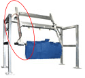
Hope the image is large enough for you to see where my dilemma is.
No problem in drawing the wires going up and down the diagonal bar. However, at the top left when the wires come from the back bar of the frame over to the diagonal support bar and motor, I seem to have a problem in getting the lines drawn correctly.
I am also having a similar problem at the where the wires leave the arm and join the motor to the left of the brush.
Converting the lines to wires, no problem. What tools do you suggest I use to draw the lines?
I am also attaching a "practice" SketchUp file. Yes, I did some exploding just to mess around with. BTW: It is a 2017 skp file.
TopBrush.skpI have also attached the original image file I am using as a reference.
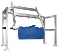
-
Unfortunately although the SKP downloads just fine the 'path' for the wire is not seen !
Another try ?Or even easier... draw the desired path of lines and arcs, then use my Weld tool to make the selected parts into a continuous curve path, and then use my PipeAlongPath tool on that selected path to specify a 'pipe' size to be extruded [and remember that a cable is only a pipe with no central 'hole' !]
http://sketchucation.com/pluginstore?pln=TIG-weld
http://sketchucation.com/pluginstore?pln=PipeAlongPath
... -
@tig said:
Unfortunately although the SKP downloads just fine the 'path' for the wire is not seen !
Another try ?Yes, it is not seen. That is the problem. I am having problems drawing the path. That is the part I need help with. I was fully expecting to use the Weld tool to connect lines. I am just having a problem drawing curved lines in 3D.

I thought maybe you would be able to click on the images and seem them larger so you could advise me.
-
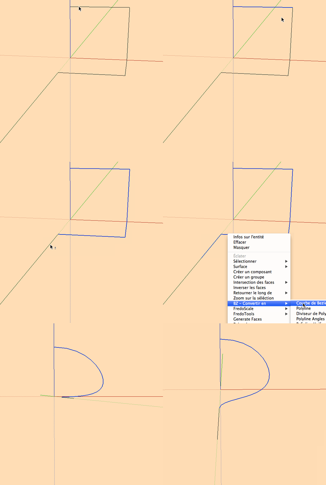
BZ tools:
-
you can also make a volumic grid for click on it with the "bezier" curves of Fredo!
-
As Pilou suggested, draw a box to help with placement of a Bezier curve. Or you can draw straight lines in the general path of the wire and use Bezier Curve to create a path for TIG's Pipe Along Path.
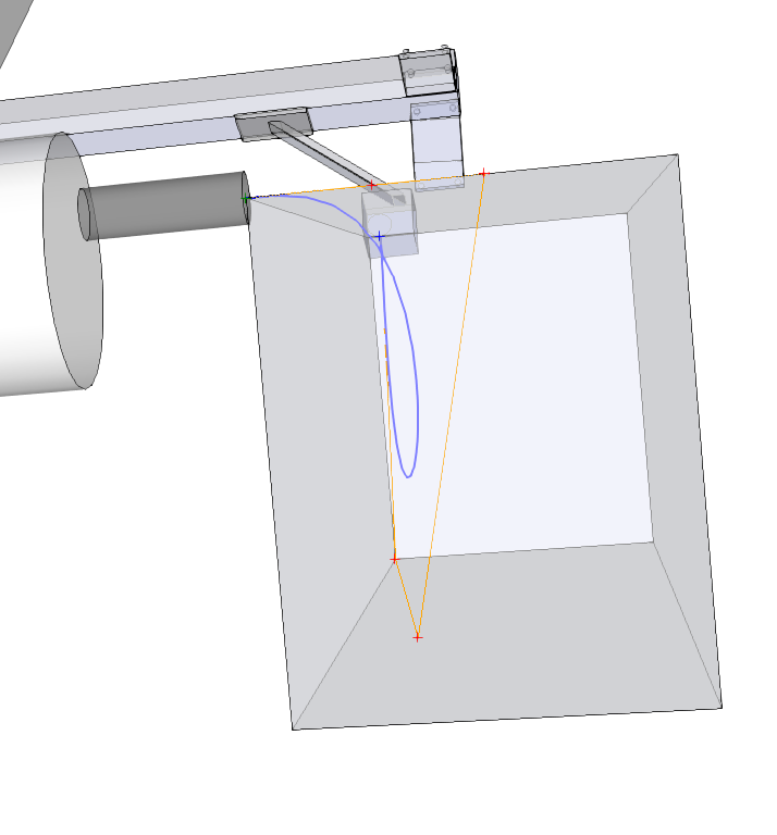
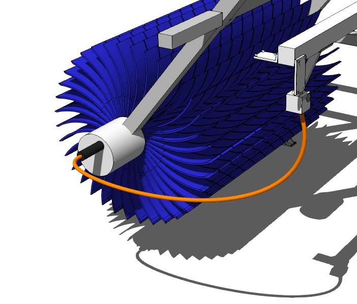
BTW, we need to get you making components on a regular basis. Too much loose geometry and too many groups in this model.

-
Thanks guys, you helped me a lot. I had kind of thought of that but had not tried it yet. Still a little "playing" to do but you got me on the correct track. I am not sure I fully understand how you did the box and drew the lines with it. I just drew straight lines and then converted. Got to experiment with various types of Bezier so I learn the difference in the types of curves/lines.
Yes, Dave, you have taught me the value of components instead of just groups. This was an old piece of equipment and I had done some exploding before I started playing with the additional items that needed to be added. I promise I will "clean it up". I need to go back and do that for a bunch of my equipment (which I do have stored as components).
When I get this one worked out the way I really want it to be, I will post a rendered version and you guys can set me straight.
Once again, thanks to all of you. I felt pretty stupid in asking the question. Should have gone with my gut but hope others may take something away from this as well.
-
OK - I did some more messing around and wanted to let you see some progress. A little hard to see but there are actually 2 cables there (one is red, the other is black).
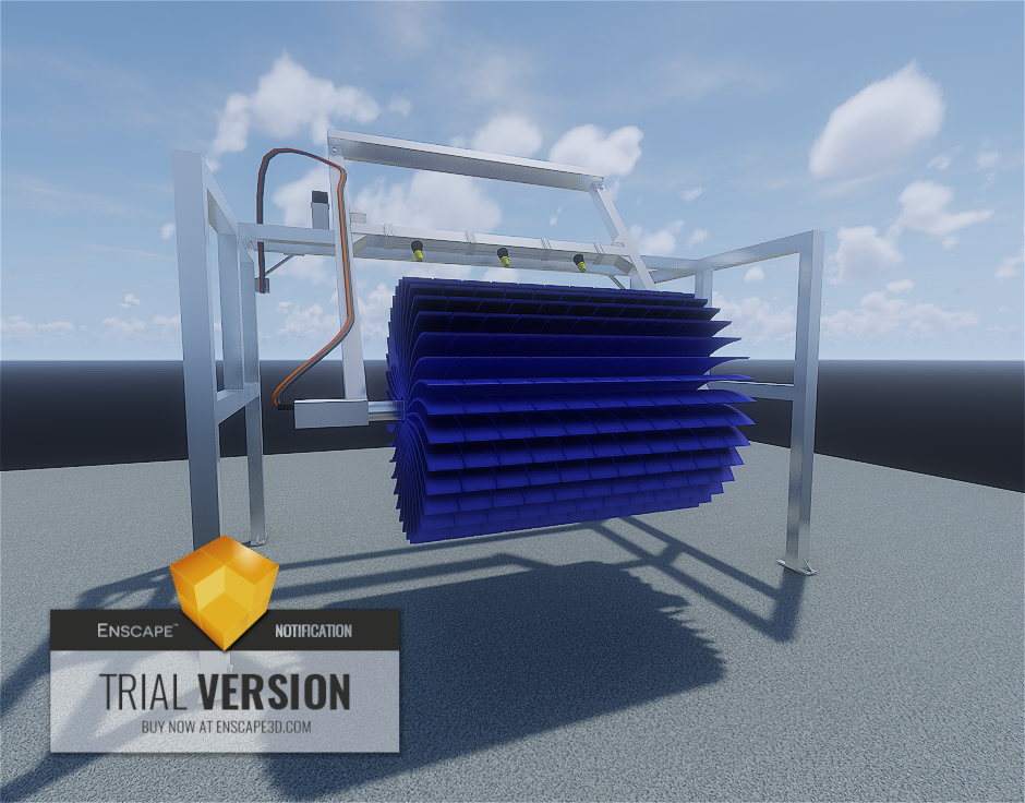
While I am not 100% satisfied, but it is a start. Will try some more messing around tomorrow if I get a chance.
As you can see, this was done with the alpha version of Enscape......
-
Good work. You wanna come wash my car?

-
Thanks Dave - I really need to play with the Bezier stuff more so that I understand better what each of the tools does. Need to go find a good tutorial that will help me learn.
At least it is a start.
-
I think Fredo did a PDF with some documentation on using the various curve tools. I could do a demo if you want although not tonight. The sand is almost all down in the bottom.
-
One last image as I continue to tweak the details a little. Think this is all for this piece of equipment though.
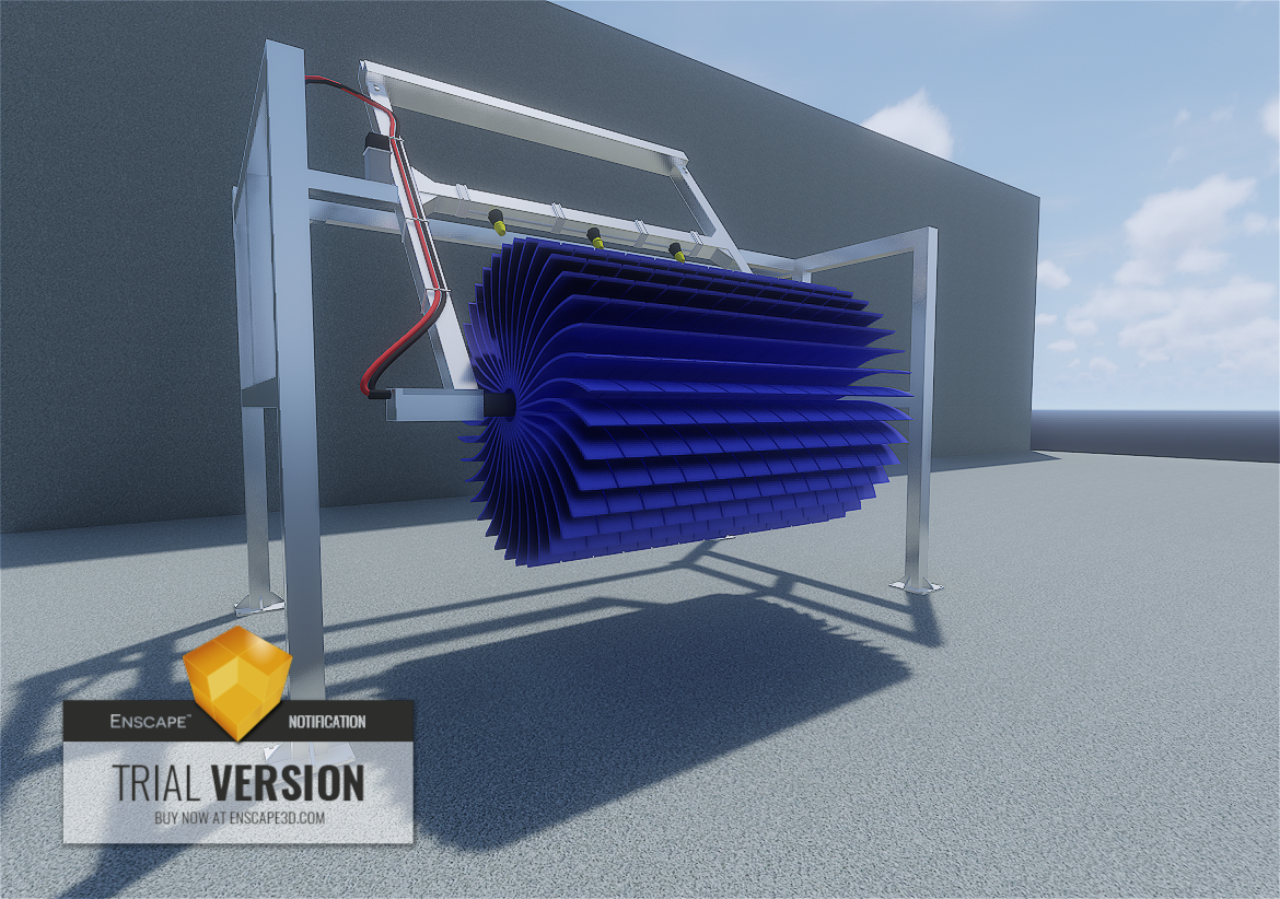
@DaveR - when I finalize this piece of equipment I promise I will go back and convert most of the groups to components. Some of the groups may stay as groups inside the appropriate component.
I have one more MAJOR task before I go start updating my equipment/component library though. I want to set up a library of standard colors/materials/textures that I apply to all of the equipment so that the frame, brushes, and other common elements are the same in each component. So, I need recommendations in how to clean up the mess I probably have in my library. In particular for layouts/models where I have multiple pieces of equipment I want to eliminate duplicates color/material/texture instances (hope that makes sense). I think I have seen a thread once before but was not able to find it that gave some steps & tips on how to accomplish this. Hope someone can point me in a direction.
Advertisement


