Foundation Plugin
-
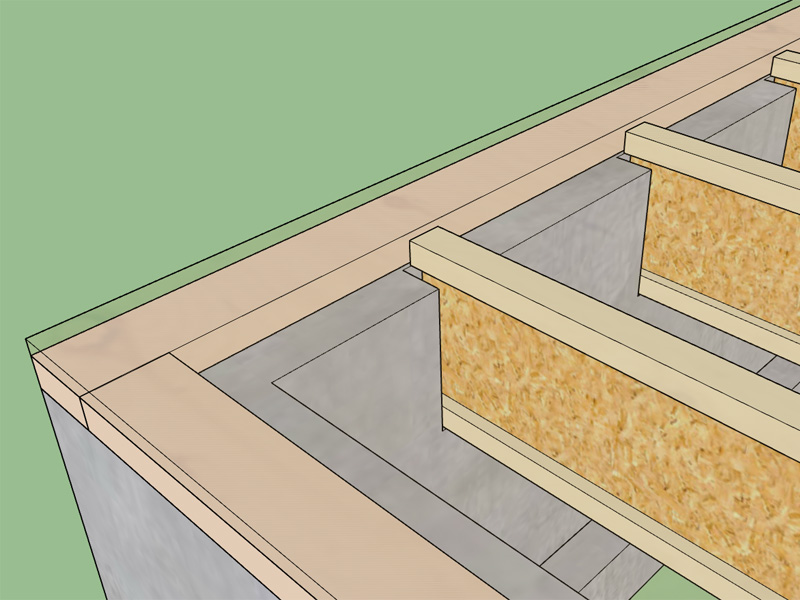
Has anyone ever seen a stemwall framed liked this?

-
Medeek,
I have placed your stem wall question in ChiefTalk which is
frequented by several active builders - designers in North AmericaChiefTalk reference:
https://chieftalk.chiefarchitect.com/topic/13289-stem-wall-detail-question-of-construction/ -
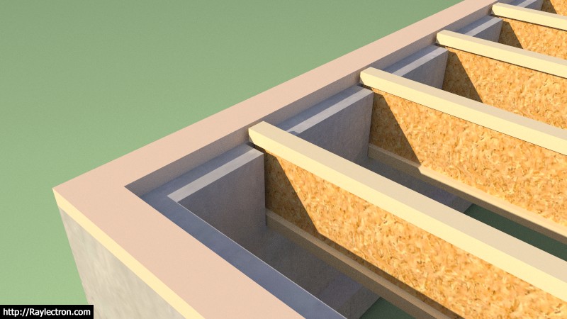
Another technique I've had a recent request on is to create slots in the stemwall that the joists sit down inside. This method dropping the joists down, even with the sill plate, seem to be fairly common in Oregon.
-
Or like this?

These two methods seem to be fairly popular in Oregon, I've never seen a floor/stemwall constructed this way any where else.

-
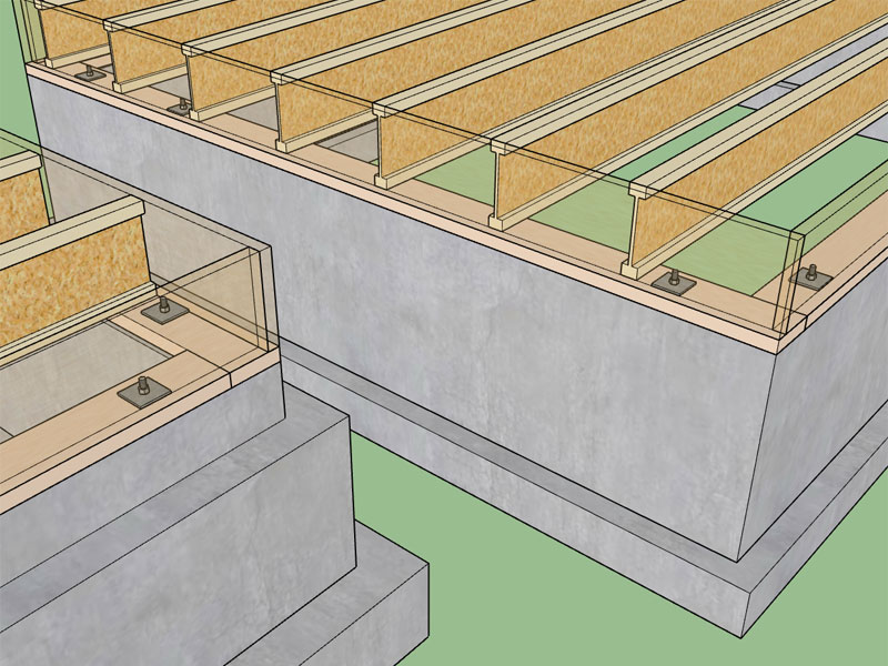
Looks like a lot of extra work. Why not just drop a single ledge for the joists? We do that sometimes in California. Put a pressure treated plate on a lower ledge. Also each joist needs some sort of anchoring to (but also separation from) concrete. There would be blocking, unless they use the concrete somehow.
-
@medeek said:
Has anyone ever seen a stemwall framed liked this?

No. Again, isn't blocking required at the ends of joists? I always see that.
We just pour a wider stemwall which narrows to 6" wide by the joists. If you are going to anchor 2x's at each joist, why not just anchor a continuous ledger to hang to? Again the framing looks overly complicated, but they must have a reason they are doing it that way.
-
Any thoughts on an advanced option that auto-inserts anchor bolts?
Options would be:
Size: 10", 12", 14"
Dia.: 1/2", 5/8"
Washer: 3"x3" Square, 2"x2" Square, Round
O/C Spacing (ft.): 6'
Sill Plate Thickness (in.): 1.5"
Distance from Corners (in.): 12" -
The argument for this construction method is the sheathing height is decreased because the rim board is eliminated. However, in my mind the cons outweigh the pros:
1.) There is a thermal bridge through the stemwall at the corner where the floor meets the wall.
2.) Stemwall construction would become more complicated and time consuming.
3.) Proximity of the I-Joist to the concrete could be problematic, requiring additional measures and more time and effort.
4.) The crawspace height is reduced making it harder for other subs to install and work in and moisture from the ground is more likely to be an issue.
5.) Nut and Washer of anchor bolts protrudes into floor sheathing and bottom wall plate, requiring additional notching.
6.) If you want to run plumbing or electrical down through the wall bottom plate and into the floor, this is nearly impossible with this configuration. -
Those are all good points. We use a similar method but use a single ledge. It's useful if you want the exterior concrete to come up higher due to clearance at grade or terraces alongside the wall. Sometimes there might be additional concrete wall as a sort of curb higher than the floor. You still have to make the min. crawl space clearance. Yes more hassles for plumbing and electrical. Nice option on adding anchor bolts.
-
I'm trying to determine if its easier to write a module that draws the anchor bolts or just bring in the component (pre-drawn). I've never brought in a component before so something I need to explore further. The other thing I feel is key is to make sure any of these minor components are modeled in such as way as to remain fairly lightweight within the model. No one is going to want to use a feature that bogs down their overall model. That is my one big gripe with using the 3D Warehouse models, the polygon count on most models is usually outrageous.
-
I need some input from the foundation and truss plugin users. I've decided to pre-model certain things like Bolts, Nuts, Washers etc... With Nuts and Bolts I'm planning on using a cosmetic thread so that the polygon count is minimal. As I've been experimenting with the bolts and nuts I'm wondering if I should eliminate the 30 deg. bevel on the head of the bolt and nut, it looks nice but adds quite a bit of complexity and polygons to the model. Any thoughts on this?
You would sacrifice some realism for a smaller model...
-
The question arises as to what will be THE INTENDED PLUGIN USE by the majority of users?
Foundation detail requiring a Realistic look for "bolts" in construction details is not high on my list.
The hierarchy of detail will depend on the "scale of detail".I would suggest users be given the following options that allow a selection:
- No bolts to be shown
- Simple bolts without bevel
- Detailed bolts showing bevel.
Hope this helps?
-
Simple bolts. More detailed will only be required in detailing, which generally are separate (highly detailed) models.
-
For now I will eliminate the beveling of bolt heads and nuts, the added number of polygons is too hard to justify and the bevel doesn't really add much when your zoomed out at building scale anyways (in other words you really can't see the bevel).
There is always an option to turn the anchor bolts on or off, that is a given. Some users may want this function others may have absolutely no use for it. It will be there if you need and want it.
For now I am going to go with 1/2" and 5/8" anchor bolts, I can always add more sizes later by request. The standard sizes of anchor bolts are per a specification I pulled from Fastenal (major manufacturer of fasteners in the US). I will start with 10", 12" and 14" lengths.For the square washers I will give an option between 2"x2" and 3"x3", with the 3x3 being the more typical I would think with the latest 2012 and 2015 cycle of ICC codes. The exact dimensions of the square washers are per Simpson Strong-Tie's offering in there wood fastener manual.
The hex nuts are per the Machinery Handbook 27th Edition.
If anyone has a metric spec. for anchor bolts (L-bolts) please send it my way and I can add in the metric equivalents.
-
I'd say for an overall building model-- as long as part is recognizable, dispense with the niceties to save poly count. Not sure how the intent of the model would be. Does anyone really expect to cut details from the overall model?. Personally a foundation model with AB and all would be specialty one-off image, so that a builder can look at either a 3d image or the SU model to visualize a complex foundation. Other than that, the real information is in a foundation plan with standard and custom details.. all full of text and dimensions and tables all 2d, and really having little to do with a full building model in SketchUp. I've yet to have much interest from others in the foundation model idea, as ultimately they must build from a set of 2d plans. I have to say the work here is impressive. I doubt however the parametric results would be that close to what our plans actually come out to representing. Many designs, when it comes to foundation anchors and holdowns are inch by inch worked out--and even then we don't illustrate every standard requirement, for example the extra bolts needed for a plate splice. Or the AB might not be shown at all since they have to be laid out by the builder based on several details and requirements.
-
I think the intent with providing the anchor bolts is partly a graphical representation and also for estimating. Ultimately the exact layout of the sill plates will drive the number and location of the anchor bolts as well as any requirements from an engineer for tightening up the spacing due to lateral loads and shearwalls.
Per the code (IRC/IBC) you are required to have at least two (2) anchor bolts per sill plate segment and the bolts must be within 12" of the end of the segment and no closer than 7 bolt diameters (3.5" for a 1/2" DIA bolt). Max. spacing is 6' o/c with 7" min. embedded.
So even if I lay out my bolts starting 12" from the edge of the foundation and space them at 6' o/c there will probably still be some additional bolts required since there will be sill plate splices (for buildings larger than 16'x16').
I've always wondered if the builders actually give this much thought as they are placing their anchor bolts.
Another question I have is one would not want the anchor bolts to clash with the Floor Joists or Trusses. Do the contractors typically layout the location of the anchor bolts to ensure that this does not happen.
Your right there are a lot of constraints on the location of the anchor bolts, hence it actually might be useful to a designer to have them in the model to see potential issues as those raised above.
-
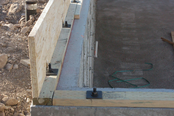
This brings to mind something I saw on a construction site a couple years ago. A contractor was framing up a garage wall and one of the anchor bolts landed exactly in the middle of one of the wall studs. A big V-shaped notched was removed from the bottom of the stud, to the point that the bearing strength of that stud was severely compromised. A 3.5" sill plate also leads to situations like this:

-
If there's a rim jst., don't use a 2x4 plate. Some builders, I am sure, work out a lot of this beforehand, especially if the general is also the framer. And in some other jobs such coordination may be impossible. If the bolt lands on a stud, I suppose extra studs can be added and the stud needed for attachment can be headed off at the bolt. Now some mechanically fastened bolts are approved for anchor bolts. Some innovation in technology is in order to be sure.
-
The 1/2" and 5/8" anchor bolts, washers and some standard nuts.
View models here:
3D Warehouse
3D Warehouse is a website of searchable, pre-made 3D models that works seamlessly with SketchUp.
(3dwarehouse.sketchup.com)
-
Version 1.0.7 - 03.19.2017
- Added 1/2" and 5/8" Dia. Anchor Bolt option to stemwall and slab on grade foundations.
- Anchor bolt lengths are nominal 10", 12" and 14", square washers are 2"x2" or 3"x3".

View model here:
3D Warehouse
3D Warehouse is a website of searchable, pre-made 3D models that works seamlessly with SketchUp.
(3dwarehouse.sketchup.com)
The anchor bolt, washer and nut are three separate files that are loaded in as components. Then the nut and washer components are inserted inside the bolt component and exploded so only the solid group(s) remain. Its pretty amazing what you can do with a robust API and a little bit of Ruby code.
It took me most of today to figure out how to do all of this since I'm in uncharted territory but now that I've got it kind of figured out it opens up the possibility for a host of other things (holdowns, windows, doors, vents etc...) for this plugin and the others I'm working on.
Advertisement


