Question: Unwanted Sections
-
 Hi,
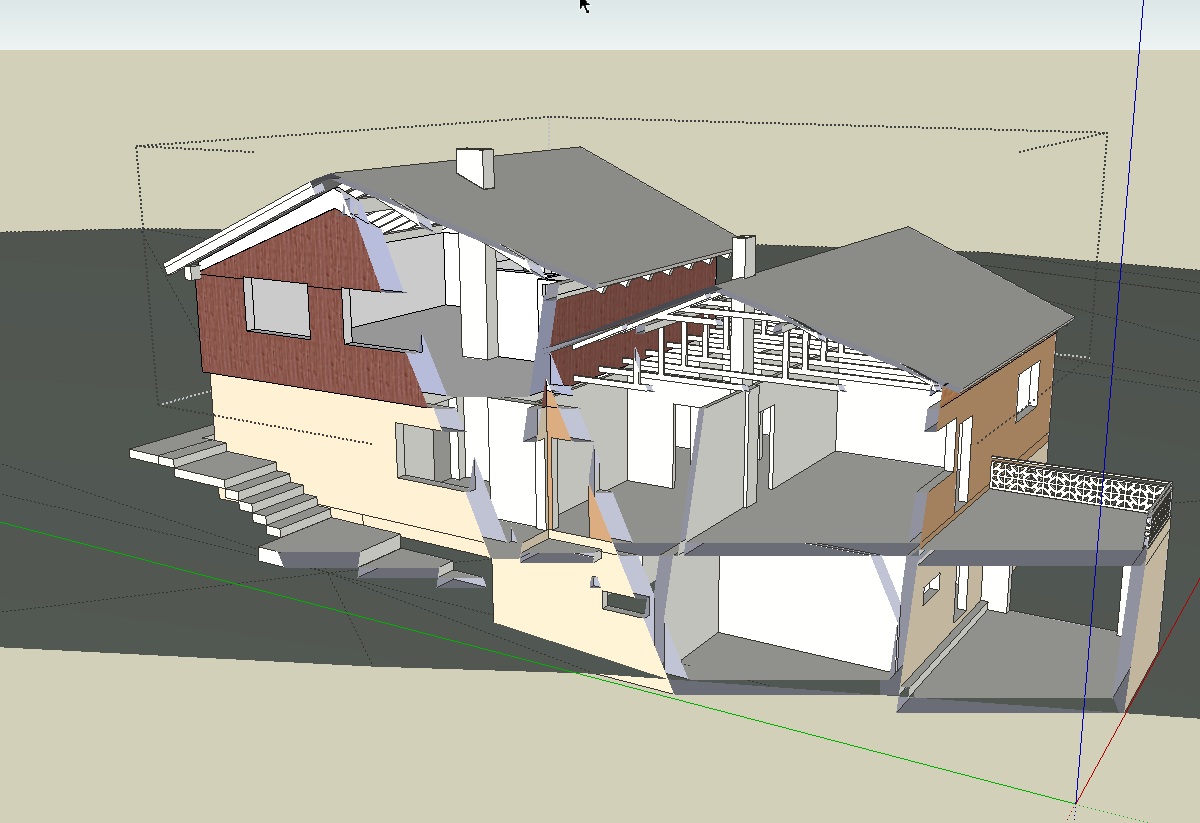
Hi,I have a question. The model shown was imported as a DWG. As soon as I open a group and zoom it, these sections appear. I have already changed the field of view but that did not help. Does anyone know a solution. Thanks in advance for your help.
Charly
-
Charly,
Not sure what is going on, but for the heck of it I exploded all of the groups and the clipping/sectioning went away. So, I'm guessing there is something going on with the grouping
-
looks to me like you are experiencing clipping. If it was an acad file that you imported the orgin that came in with that cad file may be a long, long ways away which will cause clipping. I went through this with a imported cad file recently and got some really good help here on the forum. Let me see if I can find that thread and point you to it.
I'll be back
Paul
-
http://sketchucation.com/forums/viewtopic.php?f=15&t=50812
Have a look here
-
It's almost certainly a 'clipping-plane issue' - as linked...
Geometry that is far away from the SKP's origin will produce this effect.
It's common when importing CAD data that has been 'geo-located' far from the CAD origin, and you choose to keep the CAD origin, which can put the imported objects miles from the SKP's 0,0,0.
So, either don't keep the origin OR ensure everything is visible, unlocked and all layers on, then select-all and move it by a logical picked point, and typing [0,0,0] (or [0;0;0] if you use a ',' as decimal point!)
Another more subtle issue is from sloppy CAD work where a scrap of a line is within a block [now imported as a component] and it's miles away from the main geometry, so although the model and component are located sensibly in the SKP the component is actually miles across - this is noticeable if the edited component's dotted bounding box is far bigger than it ought to be - to fix this... edit the component, select-all, hold ctrl+shift and deselect the visible geometry by fence - Entity Info will remove some things still selected, press 'delete', the bounding-box will shrink to suit the 'real' object.
Another similar issue is that the CAD import is located logically near the SKP origin BUT components made from CAD blocks have their insertion points miles away - making then miles across, but this time with not rogue geometry - in that case you can right-click that selected component and in the context-menu choose - Change Axes, pick new logical point/direction for its axes...
Yet another possibility [rare!] is that the CAD author has imported some blocks made different units, and instead of fixing them to match his current setup he has rescaled them in his drawing. This can means a component perhaps x1000 bigger than it appears on screen - so a 1m wide door might actually be a 1000m wide block ! A few of those in the model will look OK but cause SketchUp problems when calculating geometry/graphics... -
If you select only the groups and/or components of the modeled house and explode, the clipping is eliminated. Why? I have no clue.
I left the terrain and imported plans alone (unexploded) and clipping was not an issue. One thing that I did notice was when the "house" was exploded there was a dimension "20m" that was floating very far from the house, but the clipping was not an issue whether that dimension was left alone floating out there or deleted.
Hopefully these observations help someone else narrow down the culprit for you.
-
Exploding a component removes the issue - so that suggests to me that some components have their origin [insertion-point] miles from their geometry.
After exploding the container's bounds are no longer messing with SketchUp's brain !
You also have two [nested] components in the Model tab of the Component Browser - one named "m2" containing the other named "グループ#76" ???
It doesn't seem to contain much ? Just 4 tiny edges...
This might be causing or at least contributing to the issue... -
I thank you very much for your answers. Especially TIG, for the detailed instructions.
@tig said:
Exploding a component removes the issue - so that suggests to me that some components have their origin [insertion-point] miles from their geometry.
This solved the problem.
Best Regards
Charly
-
Hi,
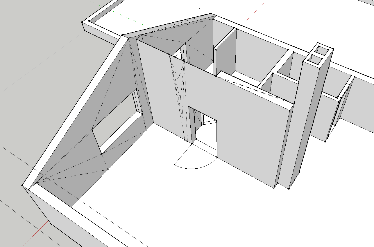
I need help again with this DWG. I'm still mad. I rebuild the entire house new based on the plan. The walls are pulled up precisely vertically. What causes these lines?
Thanks in advance
Charly

-
Can you post the file?
Chances are the planes of the walls are not flat, but that's just guessing without the file. If you go into the style menu, then edit, change the edge color option to by axis. The edges then will either be red, green or blue if they are parallel to the axes, if they are another color then the walls are skewed/warped and that is what is causing those other lines.
See if that helps.
-
Also, forgot to mention. If the model checks out and everything is true/square, then use the delete coplanar plugin, and all those goofy extraneous lines will go away. I'm not sure how to link you to the page with the plugin, but it is in the plugin sub-forum somewhere here on Sketchucation
Advertisement


