Screw threads simulated on a cylinder
-
I have used a sketchy lines material turned at an angle to insinuate threads and I've used Draw Helix, too. Recently I indicated threads on both a rod and a nut by simply copying the end circle multiple times down the length of the cylinder. this was for a situation where the printing method won't allow for a texture and I didn't need to show the spiral nature of the threads.
-
Thanks for the rapid replies!
Trogluddite, you are correct I want to make it look like there are threads on the part, no need to demonstrate actual appearance.
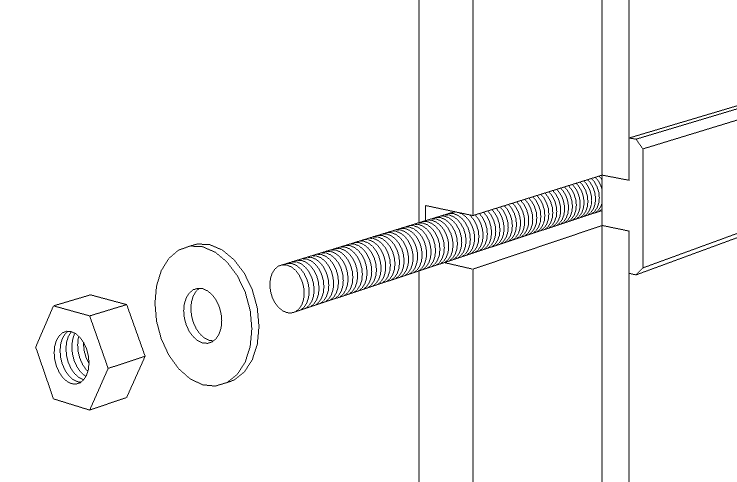
Dave R., I believe you have the answer I need. The picture you posted is exactly what I am trying to accomplish. Can you please let me know how you were able to do it. Thanks
And for the record I believe I said in my OP that I was new to THIS forum and SketchUp...not new to forums and I am fully aware of how to use the Search function. I have used Google SketchUp many times but never had the need to go into great detail until now.
-
To make those "threads" I selected the circle at the end of the rod or the hole. Then I got the Move tool and hit Ctrl (Option on Mac) to invoke the copy function. I copied the selected circle down the length of the geometry a small amount. Then I hit Enter followed by *n where n is the number of copies I wanted followed by Enter. This is just a standard linear array.
-
What I don't think is clear from Dave's excellent solution is you can minimise your model size by creating the basic rod and grouping it and then creating another circle (without face) and copying that before grouping the rod and the circles. If you don't you will generate a lot of faces with each circle created, which may not be a problem if your model is small enough.
-
Good point Trevor.
-
Excellent points gentlemen. Thank you all, I will give it a try and post my results...thanks again to all who responded.
-
To them what cares...I was able to achieve my goal by using the grouping and move/copy option. It worked great and was rather easy, thanks to everyone for your assistance.
-
Good deal.
-
It sounds like your thread pitch is too fine. spread them out a bit and you shouldn't have any problem. If you're only simulating threads there's no need for them to be spaced to the real pitch of the threads. Besides, if you put them too close together you'll just end up with the threaded thing looking black.
-
You have hit the nail on the head! I'm using a 1.5mm radius cylinder (small electrical connections I'm illustrating). The tread pitch was set at .5mm. I found I had to space the circles (thread) no less than 2mm to get it to work OK without the faces disappearing. I've also found reduceing the number of sides in the circle's used can over come this problem.
Using a 2.5mm radius cylinder (24s) would allow me to space the thread at 1mm intervals. Anything less than 1mm the cylinder faces would disappear!
Thanks Dave R for your response. This problem does not seam to happen on my Mac; but I may not have drawn treads at such a small size. I'll look into this later. The power of the CPU may have something to do with it!?
-
-
I believe what you were running into is SketchUp's inability to create very tiny faces. You can trick sketchUp into doing it however by making a copy of the component, scaling the copy up by a factor or 100 or 1000, then make the copies of the end circle at the correct spacing for the scale factor you used. When you're finished, close the giant copy and delete it. The original one will have the tiny faces it needs.
-
@ Jean : thx for the V6

Cool trick of Movie star!


-
@unknownuser said:
This problem does not seam to happen on my Mac; but I may not have drawn treads at such a small size. I'll look into this later. The power of the CPU may have something to do with it!?
SU don't love mm! Some functions are sensible at this size!

Just Scale * 1 000

Draw anything you want and if you want absolutly mm (for some cotations) make an "unscale" of 1 000
Here some ideas for some screw method
By Kito Raup
[flash=560,315:xw0a3hpc]http://www.youtube.com/v/pNTetL3Udkc[/flash:xw0a3hpc] -
I've been using the same process Dave R described above for some time. But recently I've been having problems with this process. When I copy the circle on the end of a cylinder (or a hole) the faces on the cylinder (or hole) disappear; leaving me a mesh of lines!
To get around this problem I've been grouping the threads as ArCAD-UK mentioned. The problem with this is that these threads are displayed as a thick line not thin as it would be using my first method (as I has 'profiles' set on in the styles dialog window). I output to vector to use in Illustrator.Has any one else come across this problem? I find that this problem is hit and miss! Looking back it seems to happen on more complicated items like bolts, nuts.
-
Hi all, On testing the above on my Mac OS 10.6 I had the same problems. I did find if I enlarged the 1.5mm radius cylinder by 2 (to create a 3mm radius) I could create a simulated thread spaced at 1mm intervals. I then scale the cylinder back down (.5) to give me a thread spaced at .5mm.
I need to show this detail as the items are shown at a large scale. They are being used in instruction manuals.Sorry! I did not see this topic had a second page. Dave R and Pilou have already covered this point. Dave R's point about using a copy of a component to do this task is a very good idea; Thanks Dave R.
Hello! It looks like you're interested in this conversation, but you don't have an account yet.
Getting fed up of having to scroll through the same posts each visit? When you register for an account, you'll always come back to exactly where you were before, and choose to be notified of new replies (either via email, or push notification). You'll also be able to save bookmarks and upvote posts to show your appreciation to other community members.
With your input, this post could be even better 💗
Register Login


Advertisement