Healing Multiple Bezier Curves
-
@edyuyu said:
Thanks, Mac.
I guess I have to recheck the model. I looked it over a thousand times for any gaps but found nothing, and weld wouldn't work.
'd have to check it again.
And don't worry about the size. Not event eh tallest building is that tall. And I'm not looking for a Guinness. LOL. This was supposed to be the rough sketch.
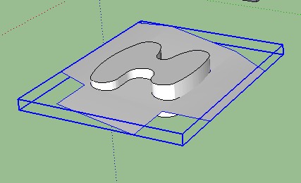
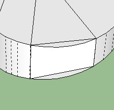
I believe the extraneous geometry you're referring to is the portion where I pulled one of the section - is that what they're called? - but I just left it there. Didn't think it would affect anything.No I did not. I deleted all the extruded model and just keep the top surface curve. The extra geo comes form the fact the arc on the top surface did not intersect properly with the surface curve. IE was not tangent.
-
I'm glad the video was useful.
pbacot has explained your problem.
Just remember that for intersect to work there has to be something for the surfaces to intersect with. -
ebyuyu
Your last model indicate to me you are not quit familiar with how SU handles Layers and I think it contributes to some of your problems. Layers in Su only control visibility and not geometry separation. Separation is controlled by components and or groups. Take for example your dxf plan view form the second model post back. It is a component but it was not assigned to a layer. Create a plan layer , select entity info for it and then assign to that layer. You can then turn on and off plus you have the geo separation. In addition that same post had layer 0 not active. All primitive geometry is drawn on layer 0 for SU and that is always the active layer and never have any other the active layer.
BTW the approach I explained to you in my first post also works for that model
Here again is the extrusion of that surface. Note: I did the cubic spline interpolation again to smooth : had to flatten also and put all layers back the 0 except for the dxf plan view.
Gallery Plan sketchmac1A.skp
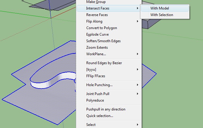
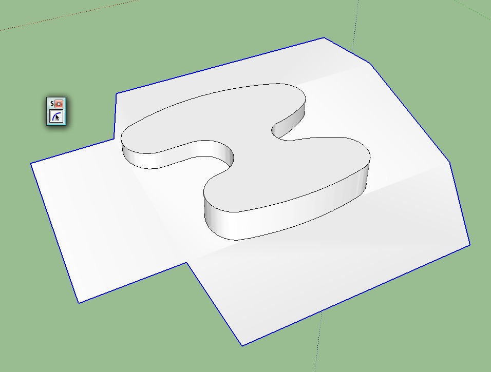
Here is an approach for the intersect:
Gallery 1_mac1B.skp -
@edyuyu said:
Thank you SO VERY VERY MUCH! That video helped A LOT!
But I have a problem. Everything worked with this new model until I tried to intersect,and it wouldn't. Please tell me what i did wrong.
Hope your cold gets better. You didn't sound bad at all. no minus points

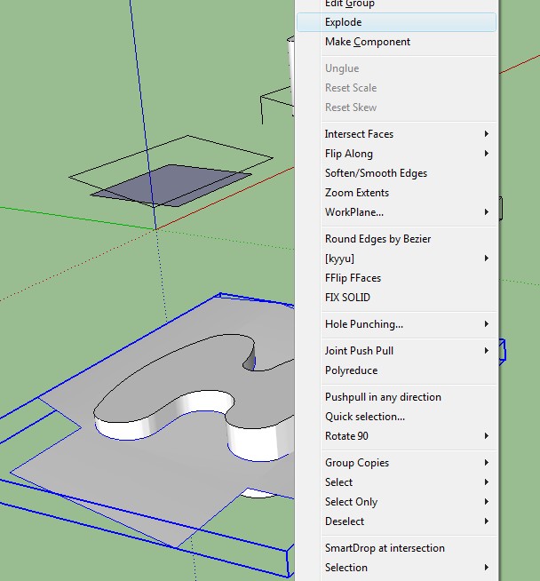
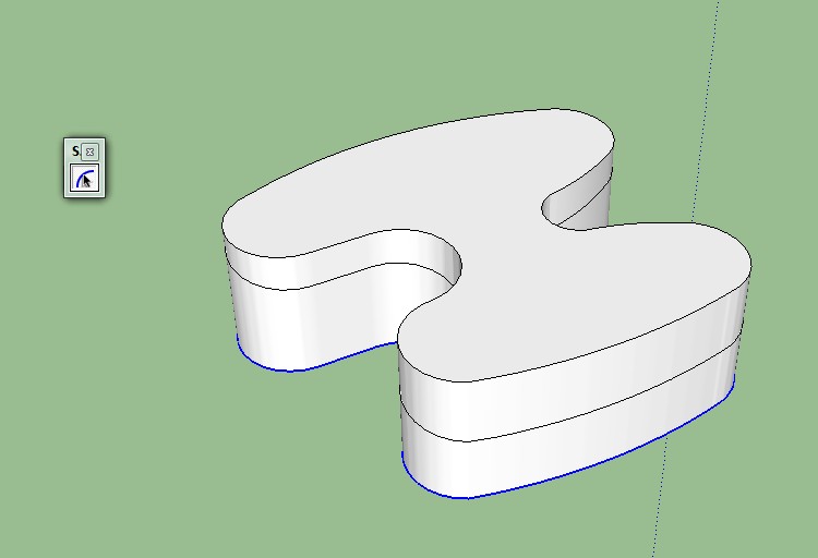
You need to extend the cutting face BEYOND all sides of the shape. You really should group the shape first but as you did not, you can still add lines to continue the cutting face all four sides, select the vertical face and intersect with model. I would then go to a side view left-select the top, group selection, then erase it. you then have to erase the cutting face and clean up the shape of extra edges, retrace a segment of the top edge to close the top face again.
[Edit: I realized later that actually easier just to remove excess piece by piece on this one.]
If you group the shape and then draw your cutting face and group that, it is easier to select and work with them separately. You can still perform the intersect function from within the shape group. What is it?
-
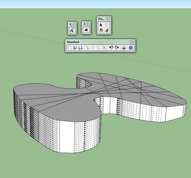
It's supposed to be a building - an art gallery. So I'm trying out different shapes. What I have in mind hasn't come out well yet. I'm think ing something in the shape of a brush stroke! #Sigh
lemme do the group thing and see how that goes...
-
Hi Mac1,
thanks a lot for your help.
i seem to have trouble opening Sketch Mac1A. could you please resend it?
I understand the procedure and it would be applicable, for tapering the model, i mean. The trouble is the tapering has to be specific in terms of dimension, from 5m to 3m. I saw that yours was approximately right in the 1B file you sent. but i need it to be exact. I just can't seem to work it! also, how do I render a face as a wireframe? thanks -
Oh by the way, what's this cubic spline interpolation you always refer to? Sorry I ask so many questions. I'm really new at this. i had also assumed layering in sketchup would work the same way it does in autocad. apparently not!
-
-
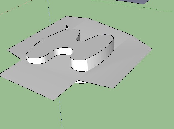
Its now look good? Right!
-
Hi Dukejazz,
Thanks for your help. But what I actually want to do is cut off the top part of the model. That face is a rectangle ... If you follow the forum from the beginning, you'll get what I mean.
-
Select the whole building-form and the grouped angled-plane and re-do Intersect with Selection.
The walls have not all intersected - doing it again will fix this.
Now edit the grouped angled-plane [double-click] and select its face, then use Intersect with Model.
Select the outer face of the now 'cut' plane and 'delete'.
Next double-click on one of the the now faceless edges and 'delete' these outer edges too.
You now have the 'roof' cutout [which is still in its group at this stage].
Exit the edit.
Pick on the curved vertical wall of the building-form that is above the roof plane and 'delete' it.
Treble click on the now unconnected flat 'top' face and 'delete' that and its edges too.
Now you have the building-form sliced at the angle and the 'roof' inside the group.
To combine them select the roof-group and 'explode' it.
Done.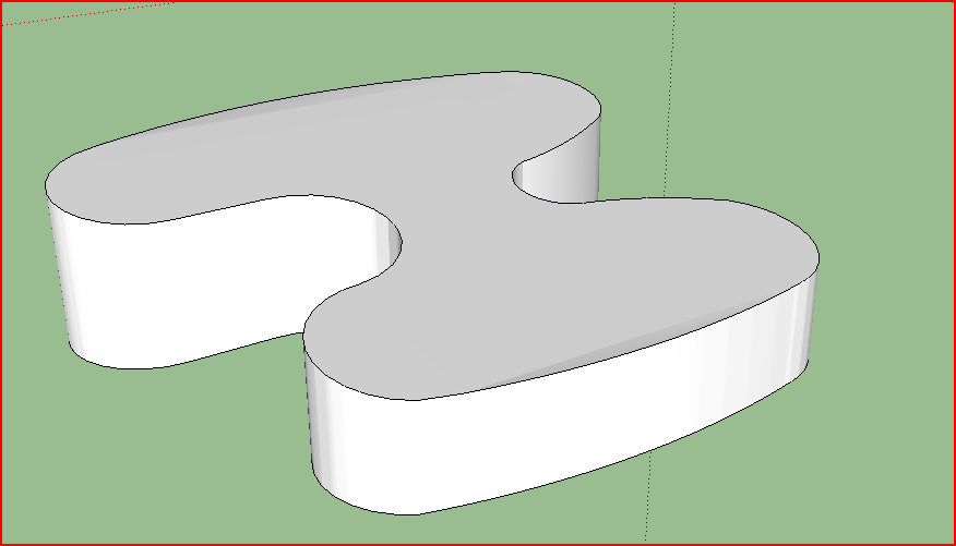
-
select curve and delete
select curve and delete
Use zoro2 to polyreduce_make vert line_erace between line_use draw tool to close side_then erace curve
Well you get the ideal, this is what I would uses
I show you four panels and fithy to go
Healing Multiple Bezier Curves
-
Thanks a lot, dukejazz!
-
@edyuyu said:
Hi Mac1,
thanks a lot for your help.
i seem to have trouble opening Sketch Mac1A. could you please resend it?
I understand the procedure and it would be applicable, for tapering the model, i mean. The trouble is the tapering has to be specific in terms of dimension, from 5m to 3m. I saw that yours was approximately right in the 1B file you sent. but i need it to be exact. I just can't seem to work it! also, how do I render a face as a wireframe? thanks1) Mac1A is from one of your first posting . It is stored and is not like e mail. I checked and still opens and looks ok to me. You are probably beyond the time frame of needing it but if you do please state what trouble opening means? Usually you will get some indication by what error message you get:
2) The Mac1B file is just a copy of what you posted. If the dimensions are not correct then that error was in the orginal file
3) Wire frame is a render mode you can select from the tool bar if you have that view set. If you go to view , tool bar and select styles then it will sow in the tool bar. It is just what the name states all you get is a line drawing of your model. When you do that then the cutting plane is very easy to select , but follow my steps to make it bigger to get the correct intersect. If you don't make it a group its geometry will stick to other parts of you model and distort it when you make it bigger -
@edyuyu said:
Oh by the way, what's this cubic spline interpolation you always refer to? Sorry I ask so many questions. I'm really new at this. i had also assumed layering in sketchup would work the same way it does in autocad. apparently not!
There are many YouTube videos for SU. I use the philosophy: Some times it is best to slow down to hurray up. IMHO you would be better served to spend some time with those to get a very basic understanding of SU ops vs the piecemeal learning process you are going through now.
Sorry for the use of the buzz words( cubic spline interpolation) but I was addressing your original topic ( Which we seem to be straying from now) of "Healing Multiple Bezier Curves". Instead of trying to explain here I suggest you do a search. Basically it is a robust method to estimate the value of a data between given data points. Look at the surface curve in some of my post compared to your early original and you will note mine are much smoother than yours.
Here is viewing for you http://www.youtube.com/sketchupvideo, https://sites.google.com/site/sketchupvideo/Home/google-sketchup-techniques. There are 100s of these so for a specific question do a search. I can almost assure you there is no question you can ask that has not been answered before. -
@edyuyu said:
Hi Mac1,
thanks a lot for your help.
i seem to have trouble opening Sketch Mac1A. could you please resend it?
I understand the procedure and it would be applicable, for tapering the model, i mean. The trouble is the tapering has to be specific in terms of dimension, from 5m to 3m. I saw that yours was approximately right in the 1B file you sent. but i need it to be exact. I just can't seem to work it! also, how do I render a face as a wireframe? thanksUpdate for you:
Remember the cutting plane in that original mac1B model was too small to cut the total extent of your model. Therefore when you make that plane bigger the high side cut gets higher and the lower gets lower. Based on you model extent the cutting plane angle must be arctan (2/d) where 2 is you height differential and d is distance
between those two points. Instead of trig you can set construction points or ref lines and then rotate the plane untill it goes those two. I would use trig since it is so easy. Note make sure you make the plane a group else you will get a sticky geometry issue.
May quick check indicates the present plane is 7.595 degs but you need 6.874 degs. You have 590 vertices in that curve and that is WAY too many and makes setting accurate point difficultUpdate 19 Feb 2012:
Update 20 Feb 2012:
Re-looked at the issue of problem getting the 5 and 3 m elevation values. The problem is the asymmetric surface will have those values occurring ~1 or at ~ most two places in the model. You can set either one very accurately, but you have to find where the fore mention points occur by inspecting you model to ID the verticals. You can use the text tool to find the max extents of the model to ID those points. I have not found a work flow that yields the 3m exact for a 5 m exact. The best I have done is [*][b]3.01390892m now ( 3.009330837m)with an angle of [*]6.76116898 degs now (6.776825767 degs)cutting plane slope and a ( point separation => L )value of 664.163112". These numbers change because I failed trig 101,. The angle should be now Asin( d/L) not Atan(d/L)
There are some very good modelers commenting to your post and hope they find what I am doing wrong. This maybe be a 32bit single float precision issue. [/b]
Hello! It looks like you're interested in this conversation, but you don't have an account yet.
Getting fed up of having to scroll through the same posts each visit? When you register for an account, you'll always come back to exactly where you were before, and choose to be notified of new replies (either via email, or push notification). You'll also be able to save bookmarks and upvote posts to show your appreciation to other community members.
With your input, this post could be even better 💗
Register Login


Advertisement