[Plugin][$] Curviloft 2.0a - 31 Mar 24 (Loft & Skinning)


-
Mac1
Neither method you suggest works for me.
I've noticed that Curviloft tends to fail when I want to form a totally or very nearly flat surface.
It also seems to be overwhelmed by large complex surfaces. It goes all rainbow on me but if I just select smaller portions without any edits, the smaller surfaces form nicely. When I then explode all the subsections, it forms 1 complete surface. A bit more work, but less aggravating than trying to find the non-existent "problem".
But all said, it is a plugin I simply CANNOT live without.
-
@jgb said:
@irwanwr said:
i wish i could use Quads too

I don't understand what you mean. Quads are just a better method to calculate and display faces on a surface. You don't actually "use" quads specifically. The pluggins (JPP, Curviloft, etc) use them when activated.
i meant the TT Quad Face tool, it seems so good so sophisticated.
-
@jgb said:
Fredo - We have A problem

The attached model is an extracted edge of a fairing. It should be a single face and all flat.
When I loft it, I get either a black face then just an empty group (thought that was fixed
 ) or nothing happens, but an empty group forms anyway. If I manually join verticies it will form a flat face.
There are no edge fragments, or gaps. The faces perpendicular are all properly formed, as well as the opposite edge to this one.
There are also no "errors" (colored lines) appearing, so I cannot find the problem.
I've had a few like this and it was easier to manually face them, but I figured you shold take a look at it.
[attachment=3:22uctz0e]<!-- ia3 -->C-Loft Problem.skp<!-- ia3 -->[/attachment:22uctz0e]
Not sure I understand the problem.
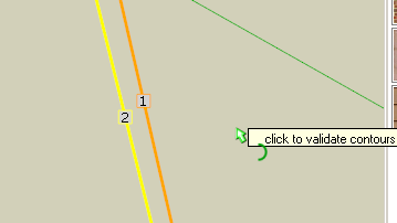
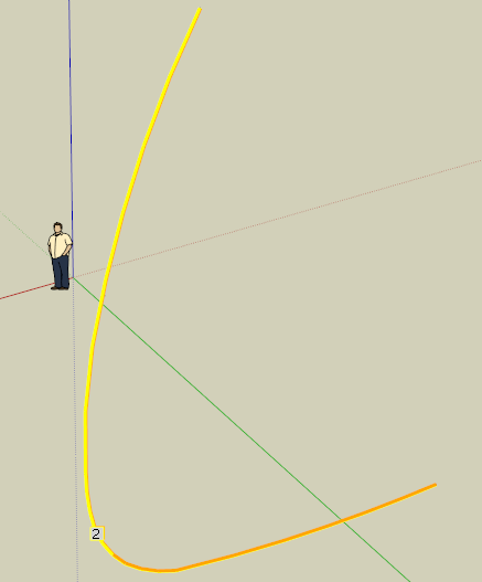
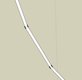
You have too identical boomerang-like profiles placed very close each other. If you select them and use the Loft by Spline tool, you get the fin skin between the two profiles.
[attachment=2:22uctz0e]<!-- ia2 -->Cloft problem small.png<!-- ia2 -->[/attachment:22uctz0e][attachment=1:22uctz0e]<!-- ia1 -->Cloft problem big.png<!-- ia1 -->[/attachment:22uctz0e][attachment=0:22uctz0e]<!-- ia0 -->Cloft problem filled.png<!-- ia0 -->[/attachment:22uctz0e]
What else do you want?Fredo
PS: When you select, make sure that you do not select the same segments twice. Curviloft does not trap all situations yet. THis is why you have a numbering for the profiles.
-
I checked and I only have 1 set of lines, so I don't understand why you see 2 sets.
And, when I do select any of the 3 modes, none form a skin.But when I select "skinning" it will give me a full black pre-skin. Hitting enter or green check leaves an empty group. If there was even a tiny gap or fragment, or double line in the selection, C-Loft would usually say so.
If you (and others) don't get the same result, the only reason I can think of is some other script in my pluggin set that you don't have is causing, let's call it, interference.
When I manually connected the opposing verticies, the skin formed, section by section, and most, but not all, the added lines could be removed without losing the skin.
Like I said above, this usually happens when I try to skin a flat or nearly flat surface.
I use "skinning" most of the time. When it doesn't work, I try the other 2 modes. When they don't work I go through the lines to find any anomalies (gaps, fragments or double lines), fix them and try again. If it is a complex or very large set of lines, I will then try to sub-divide it into several sections. Invariably the sub-sections form when the whole did not using the exact same set of lines.
I've just finished all the main fairings on my big airplane project, but over the next few weeks, I'll have a whole bunch of complex skins to create, for the aircraft's interior skins. If I do encounter any problem that persists after I fix as much as I can find, I'll post it here, not so much looking for a solution, but for you (Fredo) to analyze. Maybe there is a very subtle bug that only surfaces (no pun intended) in specific circumstances. I've been there, and that's why most of my hair has gone.

And I am not implying that I may not be doing something wrong.

-
I get the two lines also and is the reason I used the skinning option and get the same result as Fredo. BTW I measure 0.5 in apart and looks like by design ???
If this is not by design you may want to find the reason before going to a large project??
BTW I noted in the above post the tool triangulates and if you delete those faces are lost. Sounds like same result you are getting. My work flow is double click to get in context of the curve, select the skin tool, left click and select the total curve, select the green check and once the black is formed you need to click in space to complete the surface. Use outliner to see that a group is formed within your group and explode unless you want to keep as a nested group. -
@irwanwr said:
i meant the TT Quad Face tool, it seems so good so sophisticated.
Are you having problems in getting QuadFace Tools to work?
-
I did a test too without having any trouble either.
As Fredo and mac1 -
@thomthom said:
Are you having problems in getting QuadFace Tools to work?
yes, a big problem actually. it's me, myself. still unable to understand "how to", "the way", etc. Quad Face works.
as Gaieus once told me (and it does make sense), "learn to walk before you run". i might need to slow down a little bit. at least just to get back what i got from SU6 when i left it.in the other hand i can see that others can use the Quad Face very well
 .
.
from the description and clips, it is an amazing tool. i hope i'll find something to practice with and learn the Quad Face.cheers thomthom
PS: i'm able to learn and use your other tools though. material, cleanup and guide tools. tyvm for those tools.
-
@mac1 said:
I get the two lines also and is the reason I used the skinning option and get the same result as Fredo. BTW I measure 0.5 in apart and looks like by design ???
The 2 lines you refer to are the inner and outer edges of a very large 1/2 inch thick panel which is part of a fairing made of several adjoining panels. The 1st master panel itself (outer skin) was originally formed by C-Loft, then thickened with JPP to 1/2 inch. It formed all 4 edges. All the panels are rectangular (4 distinct corners) with that similar pronounced curve.
Then I selected 1 edge to become the curve control for this adjacent panel, which had a different overall shape at the top, but shared an edge. I formed that panel the same way, but had to modify it for the design. In doing so, I lost the 2 side edge faces and 1 top edge face (expected). I then closed the top 2 corners. One edge immediately skinned, but this edge and the top did not. I expected the top not to skin as it had a slightly irregular profile, but this edge should have auto skinned because it was skinned prior to the mod, and the top end was redrawn. I used C-Loft to re-skin the top edge (worked 1st time) but this edge persistently refused. I have since manually skinned it in the model.
If you want I can post the complete panel here, in its present state, but I doubt it will contribute anything to this discussion.
-
@mac1 said:
My work flow is double click to get in context of the curve, select the skin tool, left click and select the total curve, select the green check and once the black is formed you need to click in space to complete the surface. Use outliner to see that a group is formed within your group and explode unless you want to keep as a nested group.
Mac1; To keep the perspective, I'm replying separately to your 2 parts.
I do exactly that, and get a correct black face. BUT when I click to finish, I get an empty group. I've said this several times. In a previous post I highlighted this to Fredo, and he replied by acknowledging then fixing the problem. Like I said before, this seems most likely to happen when facing a very nearly flat surface.
And using SU8 Free, I don't use Outliner. To get at the empty group (to delete it) I use TT's Selection Tools.
-
Humm
Let's see. Fredo and I both get the same result. Hope others respond but that looks to me like problem was corrected. I guess there are two issues from my view point:- Why our models have two lines and yours has only one. I guess that means we are trying to skin different entities. Until that is resolved further work is fruitless. In my experience base of aerospace engineering a faring is usually a thin shell that encapsulates a payload and is the reason I thought the 0.5" thickness is correct. If I delete one of the lines what do I then try and skin? If I simply draw a cord from end to end the whole thing skins I guess I need some type of definition of the actual shell or do I miss something??
- How many more confirmations do you need?????
- Why our models have two lines and yours has only one. I guess that means we are trying to skin different entities. Until that is resolved further work is fruitless. In my experience base of aerospace engineering a faring is usually a thin shell that encapsulates a payload and is the reason I thought the 0.5" thickness is correct. If I delete one of the lines what do I then try and skin? If I simply draw a cord from end to end the whole thing skins
-
@jgb said:
@mac1 said:
I get the two lines also and is the reason I used the skinning option and get the same result as Fredo. BTW I measure 0.5 in apart and looks like by design ???
The 2 lines you refer to are the inner and outer edges of a very large 1/2 inch thick panel which is part of a fairing made of several adjoining panels. The 1st master panel itself (outer skin) was originally formed by C-Loft, then thickened with JPP to 1/2 inch. It formed all 4 edges. All the panels are rectangular (4 distinct corners) with that similar pronounced curve.
Then I selected 1 edge to become the curve control for this adjacent panel, which had a different overall shape at the top, but shared an edge. I formed that panel the same way, but had to modify it for the design. In doing so, I lost the 2 side edge faces and 1 top edge face (expected). I then closed the top 2 corners. One edge immediately skinned, but this edge and the top did not. I expected the top not to skin as it had a slightly irregular profile, but this edge should have auto skinned because it was skinned prior to the mod, and the top end was redrawn. I used C-Loft to re-skin the top edge (worked 1st time) but this edge persistently refused. I have since manually skinned it in the model.
If you want I can post the complete panel here, in its present state, but I doubt it will contribute anything to this discussion.
Please do.
I think we are working at cross purpose withoout seeing the whole picture -
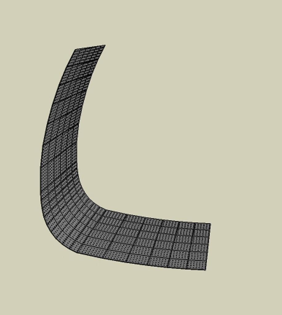 Is this some what the goal?
As I noted the 1/2" face is not flat so you cannot push pull a soften or curved face. TIGs extrude tools maybe better for this problem but need to see the total issue.
This was done loft by spline but just one side of the surface. To get the thickness it will require two steps and then reconnect the ends. -
Mac1; You are very close to the actual panel, except for a curve that you could not know of.
Please note; I am not looking for a solution. I have it. The original post was for Fredo to investigate why I get a black face but an empty group.
I've attached copies of the actual problem panel and the adjacent panel with notes. A 2nd copy has the problem face deleted and a C-Loft empty group attached.
FYI, these panels are carbon fiber composite honeycomb sandwich, 1/2 in thick. At this point in the design development, the stiffeners and structural attachments are not yet incorporated. To all you aero engineers, these panels are NOT primary structure, and are subject only to aerodynamic loads. Even so, they are stronger than they have to be, considering the planned stiffeners/internal structure that attaches them to the primary a/c structure. As such, they are considered fairings.
-
@jgb said:
Please note; I am not looking for a solution. I have it. The original post was for Fredo to investigate why I get a black face but an empty group.
I will have a look at it and come back
Fredo
PS: do not forget that Skin works on coons, that is 3 or 4 profiles in loop
-
@unknownuser said:
PS: do not forget that Skin works on coons, that is 3 or 4 profiles in loop
In Canada a coon is a smart thieving mammal.  (Racoon)
 -
-
@jgb said:
Mac1; You are very close to the actual panel, except for a curve that you could not know of.
Please note; I am not looking for a solution. I have it. The original post was for Fredo to investigate why I get a black face but an empty group.
I've attached copies of the actual problem panel and the adjacent panel with notes. A 2nd copy has the problem face deleted and a C-Loft empty group attached.
FYI, these panels are carbon fiber composite honeycomb sandwich, 1/2 in thick. At this point in the design development, the stiffeners and structural attachments are not yet incorporated. To all you aero engineers, these panels are NOT primary structure, and are subject only to aerodynamic loads. Even so, they are stronger than they have to be, considering the planned stiffeners/internal structure that attaches them to the primary a/c structure. As such, they are considered fairings.
Note jpg of strut deleted by poster.12/28-2011 2240 MST
FYI some GY70 near zero CTE tapered and curved strut. In my experience based aeroshell and fairing two differnt designs. Spent many hours on antenna range with aeroshell to reduce radar cross section so that at post planetary entry and jettison landing radar did not think it was a big target.
Glad you have solution I still get same results face forms ok.
Gday -
Mac1; that was an interesting note regarding aeroshells RCS and landing radar. Would you not have jettisoned the aeroshell high enough up so it would not be a consideration on landing?
And my term "aeroshell" applies to the outer fuselage of my big freighter, for lack of a better term.
It completely surrounds the main fuselage primary structure and is subject to aerodynamic loads only. It forms a shell or fairing around various systems such as landing gear, aux power, etc. from nose to tail.I've posted a picture of it to explain a bit of what it is about. I will not get into details for proprietary reasons. There is a lot not shown in the pic, as most details such as landing gear, support structure, systems etc are detailed on other drawings. This pic is of the master moldline and covers the main structure and secondary structures, aeroshell, fairings, etc. Otherwise the SU model gets too large to handle. I have about 20 such sub system drawings.
Think of this airplane as an Antonov AN124 on steroids. It follows that planes general configuration, but is much larger. MGTOW is about 1,700,000 lbs. Max payload is 400 tons plus fuel for 1,000 miles.
Cargo handling is optimized for standard shipping containers, stacked on the cargo deck 3 wide by 2 high by 8 along deck for 20ft ctrs or 4 x 40ft ctrs. There are 4 x 15 ton hoists on 2 overhead gantries to load/unload. And the cargo floor is completely removable for supersized loads. In fact it can swallow a complete Airbus A380 fuselage or a Space Shuttle fuel tank with room to spare.Construction is primarily carbon fibre for about 95% of the airframe. The fabrication methodology is proprietary and novel. The main fuselage tube is fabricated in one piece about 40 feet diameter and 280 feet long. The nose cone and aft cargo doors are simply cut out and finished to be mated back. The upper fuselage is fabricated the same way, cut in 2 longitudinally and serves 2 airplanes. Each half is then cut in 2 again forming the fwd and aft upper fuselages, which are mated on top of the cargo fuselage.
The aeroshell is more or less conventional panel layup. Carbon fibre skins with a honeycomb or foam core.
Anyway, this forum is not the place to discuss my design so here I quit.

-
Hello! It looks like you're interested in this conversation, but you don't have an account yet.
Getting fed up of having to scroll through the same posts each visit? When you register for an account, you'll always come back to exactly where you were before, and choose to be notified of new replies (either via email, or push notification). You'll also be able to save bookmarks and upvote posts to show your appreciation to other community members.
With your input, this post could be even better 💗
Register Login


Advertisement