[Plugin] 2D Tools
-
Running a MacBook Pro...I cannot get this plugin to work. I have had success with other plugins but cannot get this one or the cline tool to work properly. Any help is appreciated.
-
You really haven't given us much to go on in order to help you. I can tell you that I have this plugin installed on my MacBook Pro and it works as expected. This would lead me to believe you've not installed it correctly. Why not throw us a bone and post a screen shot of your Plugins directory to show us how you have the plugin installed.
-
I recall some reports about 'modifier-keys' being flaky on MACs, or them being the wrong-way-round or somehthing weird ?
If an experienced MAC user could chip I ?
I have been waiting to get some advice/fixes back on this issue for ages...However, if you just want to draw some 'clines' there are already several other tools available for this too... There was a recent topic on it and some links...
-
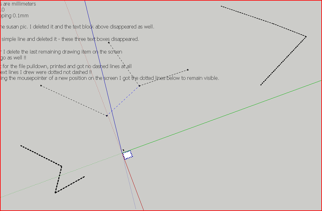
I set a 2d line style and draw a series of dashed lines (drains under and alongside a house). The lines are dashed until I stop drawing them. A single left click at the end of a line makes all the earlier ones in the set appear dashed. Then moving the mouse makes the whole set continuous. Another left click turns the set into dashed lines. A double click to end the line-set makes the set solid lines.
What is going wrong, what edge settings or other factors do I have to set ?
-
@emjay125 said:
I set a 2d line style and draw a series of dashed lines (drains under and alongside a house). The lines are dashed until I stop drawing them. A single left click at the end of a line makes all the earlier ones in the set appear dashed. Then moving the mouse makes the whole set continuous. Another left click turns the set into dashed lines. A double click to end the line-set makes the set solid lines.
What is going wrong, what edge settings or other factors do I have to set ?
You right-click in empty space to get the line-style dialog ? Thereafter any lines you 'style' match that [width/color/pattern].
Have you got view > hidden-geometry 'off' [should be]...
Can you post an example SKP ? -
Thanks TIG, for a quick response.
Here is a sample SKP. DashedLines1. I am using the Sketchup v 8.0.11752 here. There are no 2d layers that I can see. Seems to be the same in v8.0.4811.
What are the settings that could affect printing the dashed lines.
Is the deletion process that I describe on the SKP usual.Emjay
-
Your lines' dims are quite large - if you have a line 100m long it probably needs to be 1000mm wide to be visible in meaningful views!
The 'dotted-ness' depends also on the line's width...
I found that adjusting the width/style produced acceptable results
Your 'guide-lines' are not relevant to this as it only works on lines/edges...
Also you example face is 'upside down', so the 'styled edges' appear below it...
[correctly oriented to the face... but 'upside down' for what you hoped for - facing 'down' !] !
Reverse the face and you get an acceptable result...
-
Neither the line color or style is working for me. I am using SU version 8. Is there a line scale function somewhere? Didn't notice.
-
@davidterry said:
Neither the line color or style is working for me. I am using SU version 8. Is there a line scale function somewhere? Didn't notice.
How isn't it working ?
Can you please be more specific...The styled-line's width affects the spacing of any pattern's dots/dashes - so on very large scale lines you need them to be wide to get a meaningful pattern, on very short lines there might be no room to fit in any pattern if the width is too great.
The color is whatever you set it to in the dialog...
You have been right-clicking in open-space to get the style-settings dialog ?
This let's you set these values...
The 'default' is a modest-width [this varies with model-units in "/mm], the pattern is 'continuous' and color is 'black'.
Choose another width, pattern or color as desired...After you've styled a line, then later on you can select it and right-click to get the context-menu and 'Edit' the line-style: the dialog reappears and you can then change width/pattern/color as desired...
-
Hello TIG. Just downloaded and install your great plugin. But I have a problem. I read the help file, but I can't find where you edit the FILLET tool parameters. I pick both lines...but nothing happens...like, the radius must be zero or something. Where do you set the radius? BTW, I didn't have time to read this entire thread...but I will, soon.
-
@3ddetailer said:
Hello TIG. Just downloaded and install your great plugin. But I have a problem. I read the help file, but I can't find where you edit the FILLET tool parameters. I pick both lines... but nothing happens...like, the radius must be zero or something. Where do you set the radius? BTW, I didn't have time to read this entire thread...but I will, soon.
Whilst the tool is active [before you have completed the two line picking] type in the fillet segments [e.g. 6s] if you want to change that, OR more usually just the radius [default is 0 so two line that already meet aren't affected] - e.g. 6.6 in current units, then press <enter> and the fillet has those settings, you can change parameters at any time until you confirm the fillet by doing the next one or selecting another tool; note that any fillet you make thereafter will use those same settings too until you change them - even across sessions of that SKP/model...
-
Wow! Now I get it.
 Works great!!
  I've been looking for that plugin for a long time~ Thank you so much! That's what I like about SketchUcation. Immediete HELP!
Ok, got another one for you. How do I change the TEXT size in the Window I am writing this, without changing the Text size in the actual post. Old age syndrome...I CAN"T read what I'm typing. Probably because my monitors are on my console, which are 4' from my eyes. You see, my monitors are part of my Recording studio console. Heres a pic so you see why. I have two computers and three monitors, and my Skethup computer is part of my Studio recording computer too. Anyway, thanks for any help.
fitZ -
Increase the text in your browser. Usually you can do that by pressing Ctrl and Pluss / Minus
-
Hi,
or Ctrl and Mouse wheel.
Charly
-
@thomthom said:
Increase the text in your browser. Usually you can do that by pressing Ctrl and Pluss / Minus
OMG!!! How cool.@charly2008 said:
Hi,
or Ctrl and Mouse wheel.
Charly
Good grief, that works great! Learn sompin new evra dey!Thanks a million guys. Old farts need all the help they can get.
Ok, now I've got a question regarding setting the radius in the fillet tool. when I pick the tool, the default value in the measurements window is 1". I can enter a smaller value like .5, but as soon as I pick Line1, it reverts back to 1". How do I change the value of the Fillet radius? You mentioned entering in the "segment value", but the Text in the measurement window is in INCHES. Got any ideas? I really like this tool set, especially the fillet. I"d use it all the time...IF I can set a value LESS than ONE INCH. Thanks for any insight.
fitZ
-
Whenever you type in a value [into the VCB - for any tool] you must press <enter> to tell Sketchup you have finished typing - otherwise it won't know.
For example you want to use 0.25 how would it know that you weren't done typing at 0.2 - it's waiting for an <enter>
So if you want 0.5 type in 0.5+<enter> or 0.2 use 0.2+<enter> or 0.25 use 0.25+<enter>.Remember with the fillet tool it remembers the last used fillet forever - so if you last used 1" that's what it'll use next time. You can also change the number of segments in the fillet using a 's' suffix so 6s [+<enter>] sets the fillets to use six segments...
-
@unknownuser said:
For example you want to use 0.25 how would it know that you weren't done typing at 0.2 - it's waiting for an <enter>
DOH!!
 As a long time detailer...I should have instinctively known that. I discovered it shortly after I posted my question. Sorry bout that TIG.
And btw, I don't have time to read this entire thread in one sitting.
And I probably couldn't remember everything even if I could.So that brings me to another question. I tried to find an answer by searching a few tags..but I didn't find it.
Question. When I "place" a 2d Text entity on a model face, just like if you draw an entity on the face of another, the entities are "co-planar". That results in a visual anomaly where, depending on how you view the entities, one or the other will be predominant, or one will partially show, but as you move your view, it changes. Is there something in the tool set or variables whereby when you "place" the text, it "removes" the same area on the face of the other entity within the boundaries of the Text, or something to that effect? When I place 3d text, it somehow hides the plane of the entity on which it is placed, within the boundaries of the text itself. AND, you can see it on both faces of the entity. I hope that makes sense.
Anyway, thanks for the reply.
fitZ -
A piece of 2dText is actually made ~1mm above the face it glues onto.
This is to avoid 'z-fighting'.
Is there another problem ? -
@unknownuser said:
A piece of 2dText is actually made ~1mm above the face it glues onto.
Gotcha! I see that now. cool.
@unknownuser said:
Is there another problem ?
Well, there might be Give me a day or two to find one. I'm learning this tool set slowly but surely.
Anyway, thanks Tig. -
TIG
Fantastic job on this set of tools. They are an "essential set" IMHO for any architect using SU.
Thank you so much for sharing this.
Hello! It looks like you're interested in this conversation, but you don't have an account yet.
Getting fed up of having to scroll through the same posts each visit? When you register for an account, you'll always come back to exactly where you were before, and choose to be notified of new replies (either via email, or push notification). You'll also be able to save bookmarks and upvote posts to show your appreciation to other community members.
With your input, this post could be even better 💗
Register Login


Advertisement