Problems doing a curve
-
Hello,
Have carefully started drawing a clone of the Jamo R909 Oben Baffle speaker. It can be seen here and here.
Yes, I am considering building the clone eventually in real life, but want to visualize it first in Sketchup.
-
I don't understand how to make the curved baffle?
-
I also don't understand why some surfaces are not "filled out", like the sides and top. That makes me think that Sketchup and I don't agree on the fact that the baffle is one piece.

Here is what I have so far (only just begun but already have problems).

-
-
-
Here's some ideas
 Note that to make double-curvature surfaces like the top etc there are tools like CurviLoft and EEbyRails... BUT you can simply use a Style that shows End-Points and have Hidden-Geometry temporarily set to be 'on' and then you just hand-stitch pairs of vertices across the required surface as triangles that will auto-face... I suggest you make it out of grouped pieces or components since that separates geometry and makes life easier...
 -
-
Elisei and Jean Lemire > Thanks for the pointers. Good suggestions. It's sometimes difficult to get "a good start" when not so experienced in Sketchup/3D modelling.
Tig > I'll try to work my way through your suggestion, however it looks like I may be in over my head here...
-
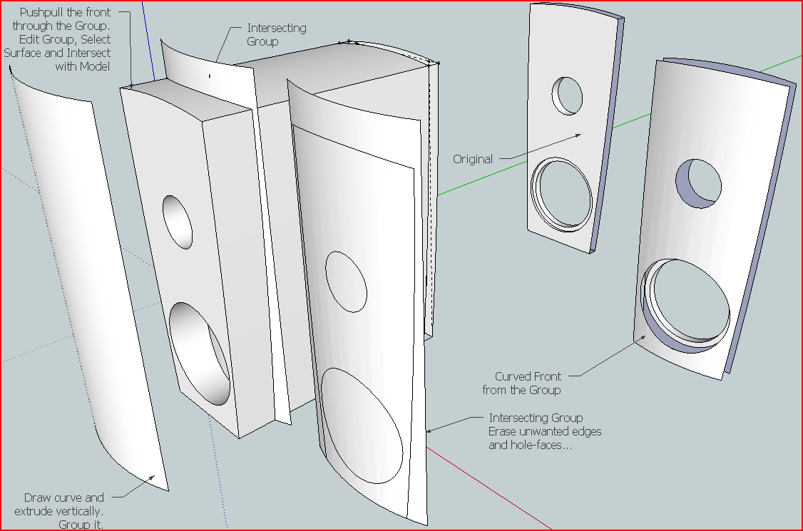
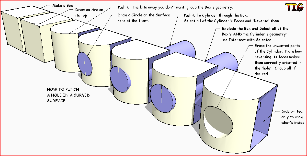
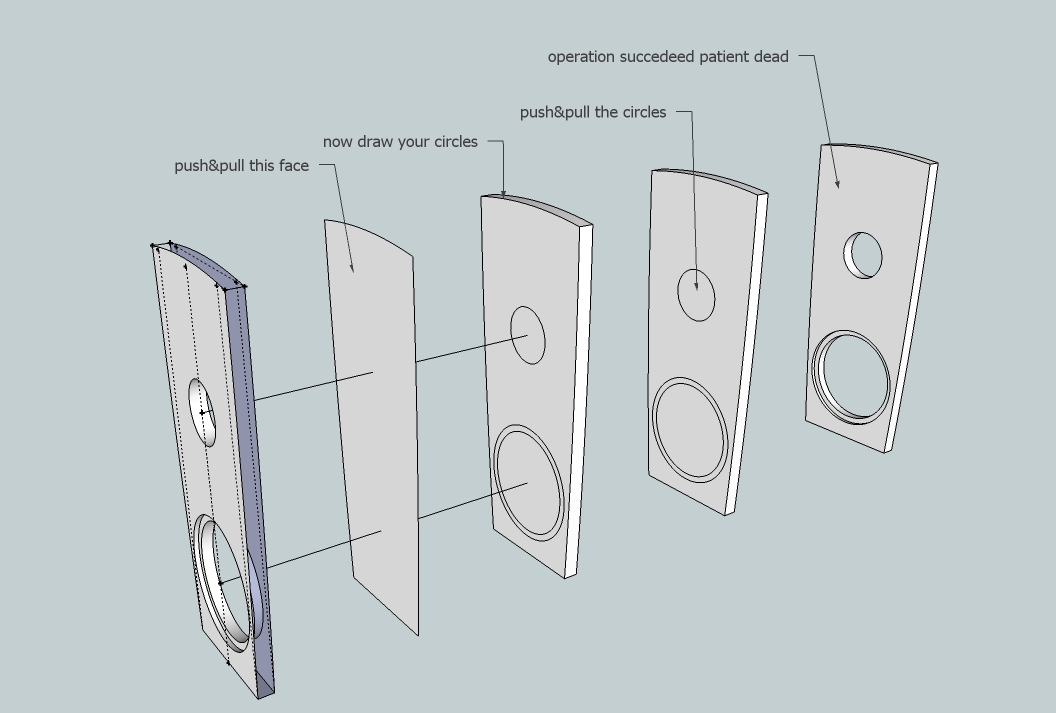
This is another way of making a punched hole in a curve surface
-
Tig > I have problems understanding your instruction from 21 Jan 2011 16:53, where it says "Draw curve and extrude vertically". I don't understand how to do that?
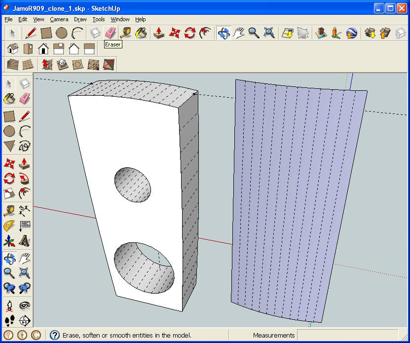
Edit: Ended up drawing it by hand, but don't know if there is an easier way? Here is the model now with hidden geometry 'On':
-
@gumleguf said:
Tig > I have problems understanding your instruction from 21 Jan 2011 16:53, where it says "Draw curve and extrude vertically". I don't understand how to do that?
Edit: Ended up drawing it by hand, but don't know if there is an easier way? Here is the model now with hidden geometry 'On':
[attachment=1:1yx0p6rf]<!-- ia1 -->gbl3232.JPG<!-- ia1 -->[/attachment:1yx0p6rf]
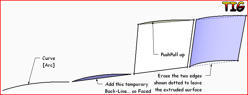
If you want to extrude a curved face vertically add a temporary 'back-line' so it makes a face, then PushPull that face up as desired. erase the two edges corresponding to the temporary back-line and its extruded counterpart. You have an extruded curve as a surface...[attachment=0:1yx0p6rf]<!-- ia0 -->Capture.PNG<!-- ia0 -->[/attachment:1yx0p6rf]
-
Arh, it's that simple. Nice.
This is where I am now - clearly I am doing something wrong.
B.t.w. it's on purpose that a "bass cylinder" shoots out from the back.
-
You must have moved the cylinders when you adjusted it and it distorted the shape. Those extra edges are indicators of this (from the autofold). I do not know how you ended up with the missing faces but maybe also because of this.
Have you got a version beforethe intersection?
-
Of course it won't connect as that shield shape is not only a curved surface but its edges are all curved, too. TIG's example is good only when all the edges are straight. (Or else I misunderstood something)
Is this that you want to end up with?
-
Okay.
Tried again following Tig's instructions more carefully. This is where I am now. Do i simply make a copy of the curved group and then connect the two via lines, or...? Tried that but it doesn't seem to "connect" the two curves.
Edit: Didn't quite understand this at first bt since my curved surface isn't the same width at top and bottom, the top and bottom isn't the same "depth" either. Hmmm... Sure glad I wanted to do this in Sketchup before I started building anything!

-
Gaieus > Almost. I can get approximately that far too now. However, I would like to end up with something like this.
Thing is though that it's narrower at the bottom (420mm) than at the top (520mm). This also makes the model "deeper" at the top. I had not noticed that 'til now.
-
To illustrate my point.
Two groups are facing each other. I "just" need to connect them, but can't work out how to.
-
The whole thing is just 30 mm thick. Should the max top thickness be 520 mm?
-
I quickly made this from the one face.
Switched of Hidden Geometry.
Removed the 'holes-surfaces'.
Selected all Surface/Edges
Use EEbyVector to extrude it backwards by ~50mm.
The 'sides' are made, but the 'back' is missing at this point.
Copied [Move+Ctrl] the front Surface and placed it on the back.
Selected that Surface and Reversed it so all faces are then 'out'.
Selected all and Smoothed...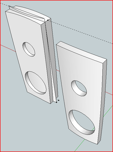
-
Gaieus > Not sure I understand?
Bottom width is 420mm, top width is 520mm. Space between the two (depth) is 50mm.
-
TIG > That's 99% procent done. Sweet! I'll try to follow your instructions, and see how far I get.
You guys rock!
-
Tig > Tried following your instructions and ended up with this. It looks correct except that when I use EEbyVector to extrude it backwards by 50mm my model gets "sliced up". I finished and also pasted the back to it and reversed it, but when smoothing the model the "slices" remains:

-
Ah, OK, I thought you meant the thickness of that plate...
Hello! It looks like you're interested in this conversation, but you don't have an account yet.
Getting fed up of having to scroll through the same posts each visit? When you register for an account, you'll always come back to exactly where you were before, and choose to be notified of new replies (either via email, or push notification). You'll also be able to save bookmarks and upvote posts to show your appreciation to other community members.
With your input, this post could be even better 💗
Register Login


Advertisement