With any plugin to make this model
-
Since I don't know...
It appears there's a valley in the corner. How do you draw that? Do you split the form into smaller sections, maybe quarters and create the lattices on each before assembling them?
-
pilou can you make tuto for this exemple plz
tuto with pictures thanks pilou -
-
Is that more clear?
I can't be more explicite
Of course you can take four different curves (Profil, rail,rail, profil)
Click image if scrollbar
If you want only circular tubes
for the perimeter use
Extrude Edges by Face always by Tig
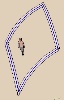

Of course in your case you must make
the 2 passes with the rectangle
Then perimeter with circle
-
look this one
my example ant the tut image by Tig
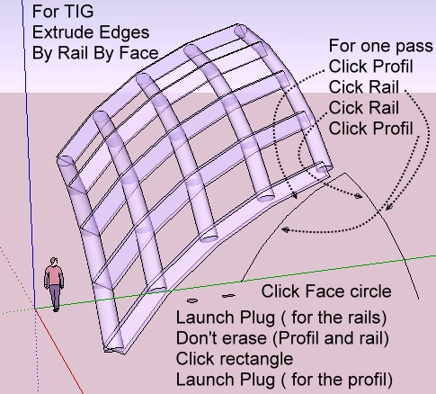
Extrude Edges By Rail, by Face
You must have "sections" of your propagaded module
That are very powerful plugs! (here only with a circle)
(here click one profil, rail, rail again, profil again
Click image if scroolbar)
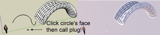
So a little circle and a little rectangle in your case in 2 passes!
-
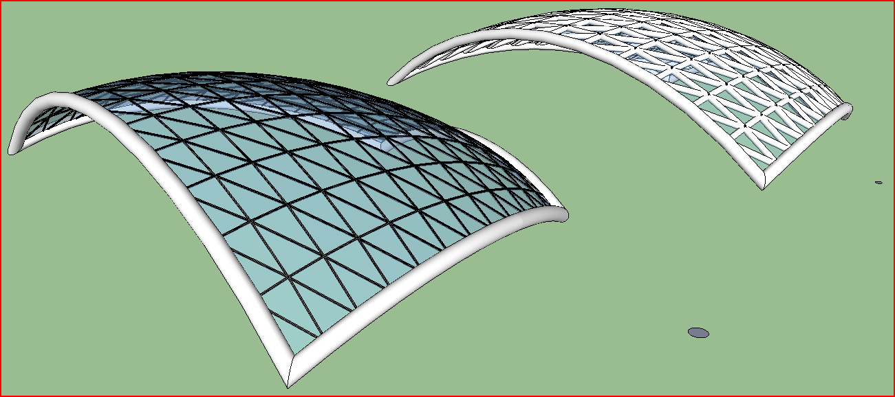
Actually I used 'ExtrudeEdgesByRailsToLattice' and four curves - profile/rail1/rail2/melding_profile - to make the glazed panels with rectangular glazing bars and glass... and then used the same four curves selected with a selected flat circular face in 'ExtrudeEdgesByFace' to make the tubular edge beams...
As Rich seems to have done [thanks by the way - much more relevant example than mine...]
-
i make model skp , i make form with EEbyRailsToLattice , but i havnt rond beamsolone et rectangular beams with EEbyface
-
You have a small form, rescale it so that it's a more realistic size.
A facet size is ~250mm but 2500mm would be more realistic.
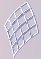
The EEbyRailsToLattice will make a framed set of glazed panels.
Make the segments a realistic size ~1m to ~3m and then you specify the glazing bar dimension in the dialog after picking 3D [you don't need to 'draw' a rectangle ??].
You can also set the pane parameters and the frame/pane materials.
After that group is made, move the grouped glazing to one side by a known amount, and then use EEbyFace - select all of the 4 curves and a flat face - a circle of a realistic radius - say 150mm - and a tubular circular cross-section beam will be added around the perimeter. Move the glazing group back into place... -
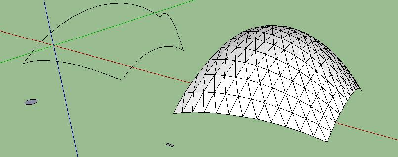
Here are examples using EEbyRailsToLattice to make regtangular-section framed panes and then EEbyFace to make the perimeter...
AND the alternative of EEbyRails to make panes as a mesh only, then EEbyRailsToLattice [Profiles+Rails, Lines Rails+Profiles+Diagonals] to make an edges only set and then EEbyFace on those edges and a small circular face to make the circular frames too. Some intersecting later you have this...
 fffffff01.zip
 -
thanks mr TIG
-
Tig,
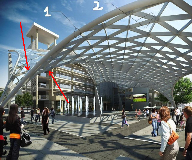
Is there a way to land a predefined component at each connector location as in the original photo?
Thanks
lapx
-
@lapx said:
Tig,
Is there a way to land a predefined component at each connector location as in the original photo?
Thanks
lapx
Like a 'connector' shaped like a 'cylinder' ?
No!
Not easily... but Chris Fullmer has a tool to add components onto a seelcted object... so it's no a million miles to have a 'connector' component with a correctly place origin that is dropped onto every node of a mesh made with EEbyRails so if you did the mesh that way you have one already [you might need to erase edge instances] ?
If you used EEbyRailsToLattice, although you simply make a EEbyRails mesh separately add the 'connectors' and erase that mesh-group on completion...
-
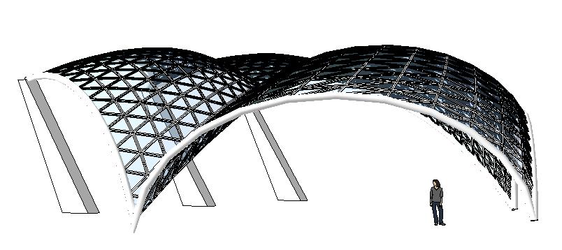
TIG , this picture is the render with vray max but the modeling is with sketchup
very nice renderong is from free agent ,
do you use mr TIG your rendering vith vray max or vray sketchup ? -
Tig,
I was thinking along the lines of Chris's script which locates a component on every face. I take it would be very difficult to align the connector or component "radial" to the joint.
Thanks,
Hello! It looks like you're interested in this conversation, but you don't have an account yet.
Getting fed up of having to scroll through the same posts each visit? When you register for an account, you'll always come back to exactly where you were before, and choose to be notified of new replies (either via email, or push notification). You'll also be able to save bookmarks and upvote posts to show your appreciation to other community members.
With your input, this post could be even better 💗
Register Login


Advertisement