[Plugin] Extrude Edges by Faces
-


Copyright 2009/2010 (c), TIG
All Rights Reserved.
THIS SOFTWARE IS PROVIDED "AS IS" AND WITHOUT ANY EXPRESS OR IMPLIED
WARRANTIES,INCLUDING,WITHOUT LIMITATION,THE IMPLIED WARRANTIES OF
MERCHANTABILITY AND FITNESS FOR A PARTICULAR PURPOSE.extrudeEdgesByFaces.rb
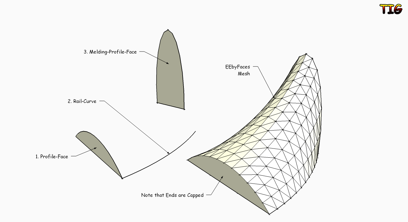
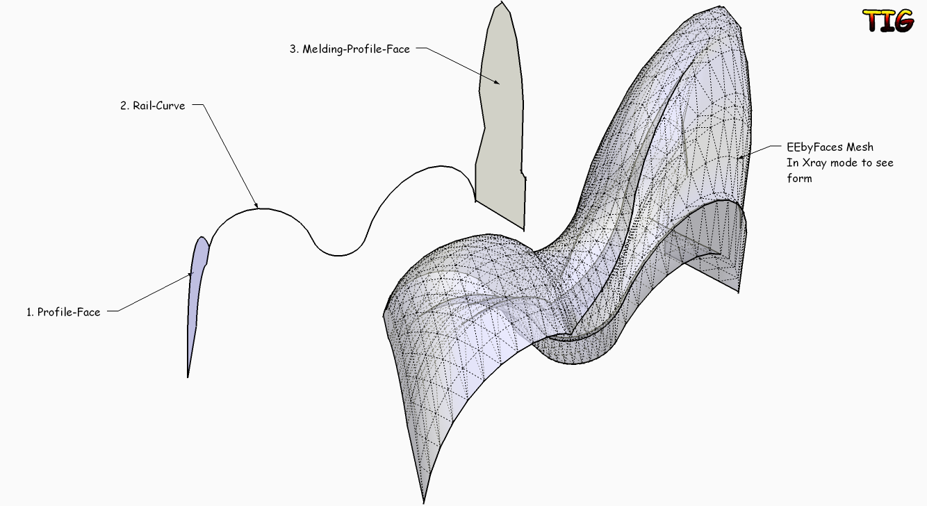
Extrudes an 'initial-profile' Face along a 'rail' curve to form a
faced-mesh group, a final 'melding-profile' Face option can control
the mesh's final form.Usage:
Make 1 or two Faces to use as the Profile/Melding-Profile.
The 3D location/orientation of the Faces is important - see below...
Any 'inner loops' [holes] in Faces are ignored.
To make a 'hollow' tube-like extrusion face the two - ring & hole -
extrude separate forms ensuring that the inner in 'inside out', then
merge the groups/intersect and erase the unwanted end 'caps'...
Make a 'curve' (Arcs/Beziers/PolyLines/Welded-Edges etc) to use
as the Rail.
These will represent the 'Initial-Profile-Face', the 'Rail', and the
'Melding-Profile-Face'.
The 'Initial-Profile-Face' is best sharing a common vertex with the
'Rail': if not it will be 'relocated' at the Rail's start to suit -
the nearest node on a Face's edges to the Rail will be used as a snap.
You are asked for the 'Melding-Profile-Face': you can pick on
the 'Initial-Profile-Face' again to form a simpler mesh from just
that one Face, but using a 'Melding-Profile-Face' means that all of
the intermediate Profiles will have a proportional 'melding' between
the 'Initial-Profile-Face' and the [Final] 'Melding-Profile-Face'
along the Rail's intermediate nodes...
The location of this 'Melding-Profile-Face' also affects the result,
it is best sharing a common vertex with the 'Rail': if not it will be
'relocated' at the Rail's end to suit - the nearest node on a Face's
edges to the Rail will be used as a snap.Run the Tool from Plugins > 'Extrude Edges by Faces'.
or click on Toolbar 'Extrude Edges by Faces'.
Activate this Toolbar from View > Toolbars if not loaded.
Follow the prompts on the VCB.
Pick the Faces and Rail Curve in the order instructed...
First pick the 'Initial-Profile-Face', then pick the Rail's Curve.
Finally pick a 'Melding-Profile-Face', or you can pick the
'Initial-Profile-Face' again for a simpler mesh form without a fixed
final-profile-face form etc.
After selecting these faces & curve it auto-runs the mesh-maker...
A grouped triangulated mesh is made based on these faces & curve...
The 'ends' are also 'capped' with faces.
Then there are dialogs asking for Yes/No replies...
If you want to 'reverse' the faces in the mesh.
If you want to erase any 'coplanar edges' in the mesh.
If you want to 'smooth' the edges in the mesh.
You can Undo these steps individually immediately afterwards...NOTE:
Multi-segmented edged faces increase processing time exponentially...
the mesh WILL eventually be made, but the screen might 'white out'
and it might appear to stop for several minutes... but it is working...
Profile-Faces with the same number of segments/edges or with
them as simple 'multiples' will produce the fewest facets.
It is sensible to 'match' the segments in profile-faces,
otherwise a mesh can become VERY faceted or possibly uneven -
and also it might take ages to make.
However, using say a 'square' face melding to a 'circular' face will
necessitate auto-divisions to match the circle's segment count.
For example, for two faces' edge-sets their segments for each part of
a rail's curve are dictated by the most segmented set:
10 + 20 segments=20 x 2 = 40 facets
10 + 10 segments=10 x 2 = 20 facets
10 + 7 segments=10 x 2 = 20 facets
10 + 3 segments=10 x 2 = 20 facets
[ 3 is the minimum edges a face can have ]
The lesser segmented edge-set will always have some of its segments
re-divided to match the more segmented ones segments. This
division is spaced evenly for edge-sets that are segmented as
multiples, but this can only approximate to 'even' otherwise...For a rail that is to be 'linear' draw an Edge & Divide it as needed
equivalent to the number of 'facets' required or to match the other
rail, then 'Weld' the pieces together into one 'straight' curve.
If you want a single Edge as a rail then make a single segment
Polyline with BZ Tools, or make a Curve out of two edges [with Weld
etc] and split the Curve with another perpendicular Edge and Erase
this and the unwanted Edge in the Curve - then you have a Curve with
a single Edge - alternatively Divide the Edge into two and get a
seam in the mesh - you can always use a 'Erase-Coplanar-Edges' tool
to minimize the divisions later or you can always add back any lost
triangulation by using the 'Triangulate Quad Faces' tool...
Occasionally Curves made from welded/re-welded/re-re-welded[!]/etc
have vertices in an order that can be unexpectedly convoluted
and create weird results - if you remake the Curve from scratch
it should be OK. Sometimes cutting and pasting-in-place or
grouping and exploding a problem curve can also fix it for use...Donations:
Are welcome [by PayPal], please use 'TIGdonations.htm' in the
../Plugins/TIGtools/ folder.
OR
Version:
1.0 20100219 First release.
1.1 20100220 Color coding of picked faces/curves added.
ProfileFaceEdges=Cyan
Rail=Magenta
MeldingProfileFaceEdges=DarkCyan
1.2 20100222 Tooltips now deBabelize properly.
1.3 20100330 Rare glitch with self.xxx fixed.
1.4 20111023 Smooth now ignores edges with only one face.To download the files for this tool go to this thread http://forums.sketchucation.com/viewtopic.php?p=217663#p217663
-
tig. excellent plugin. thank you very much.
I have some queries.
watch the video.
I see two problems-
The mesh is generated to the side of the path curve.
should be generated in the center? As extruded by face -
The faces are not automatically aligned with respect to the path curve.
the faces are flat
Perhaps the two options might exist?Flat faces
Faces oriented curve on the tour?
it is possible to correct?

-
-
tig apologize.
do not quite understand what you say.
can place a graphic example "?My idea is that extrudeedgesbyfaces work equally = that estrudeedgesbyface but with two faces and a rail
-
The faces are located at the nearest points on their edges to the rail.
Thereby you control their orientation and form by putting the required point on their edges nearest the rail start/end. The face can also be rotated in 3D which will affect the form too.
We could have an optional Cpoint or use the Face-bbox-center but I feel this is too complex - especially since 3D faces are allowed ?
To get the sort of forms you suggest perhaps you can place the faces at the start/end of the path and move a face so as to distort the rial-curve, then run EEbyFaces ???
I did think about angling the profiles as we went but it's complicated as the 'face' will need to turn by the bisector of the angle between the two edges ? I'll sleep on it...

-
-
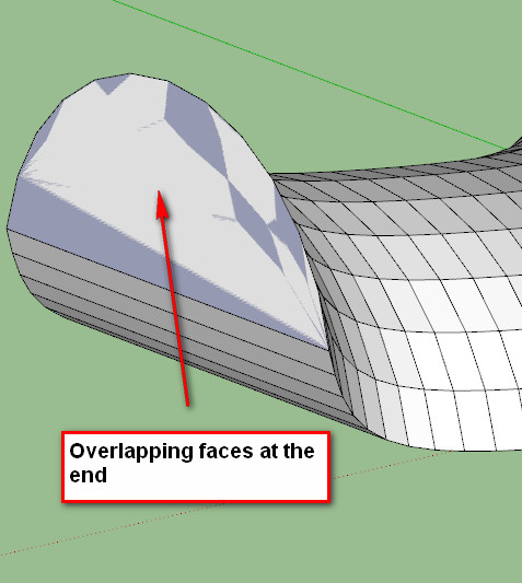
So stupid - it was the original melding face!!!


Great tool!! -
I left it as a group with the original faces remaining - explode the group to get the faces to merge back together - though one might then be reversed?

-
another example of what could be its plugins.
[flash=800,600:1poz4zaw]http://www.youtube.com/v/K8fA4TItuCA&fs=1[/flash:1poz4zaw]
generated with the same geometry:
1 - draw metal
2 - patchface
3 - extrudeedgesbyface
4 - Extrude Edges by Rails -
Thank you So much TIG for that new tool.
We see You producing with the power of an iron horse (I can't imagine where you are finding the time!) a complete set of amazing and so necessary Extrusion tools.In the present case, it seems that Kirill have developped a very similar tool: [Plugin] 2 Faces + Path ver. 1.5. What do you think ?
I am going to watch for differences, but unlike you I always run after time.
very friendly, simon
-
Tool has been updated -
1.1 20100220 Color coding of picked faces/curves added.
ProfileFaceEdges=Cyan
Rail=Magenta
MeldingProfileFaceEdges=DarkCyan
See here for download link http://forums.sketchucation.com/viewtopic.php?p=226249#p226249 -
I always appreciate your works!
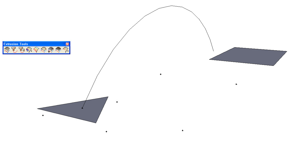
But I have the problem that after running EEbFaces,
there is no results through mesh-maker(?).
I got only some cpoints such like the attatched image.Could you explain what's wrong?
Sincerely.

-
Without the skp - it's a 'no'...
BUT two 'flat' faces can produce odd results - especially with an unmatched segment count to the faces' edges.
Have you tried welding the faces' edges into curves and using EEbyRails instead with the 'arc' picked as both paths ?
Or EEbyLoft on these faces' [now] curved edges might give the result you want...
Or wait for Fredo's CurviLoft which seems more stable for problems combos like these
-
Here's an update http://forums.sketchucation.com/viewtopic.php?p=226249#p226249
Smoothing now ignores edges with only one face... -
-
@unknownuser said:
Seems there is a little glitch ?
Melding profile is just the first profile scaled
You have that in your two faces !
Isn't that what it's supposed to do?
Change the second face you get a different result - see my screengrab.
It would probably be a better idea the place the faces at the start end of the rail too ?
-
The little "flats side" disapear/transform along the path!
But yes put the forms on the path resolves the problem

-
@unknownuser said:
The little "flats side" disappear/transform along the path!
But yes put the forms on the path resolve the problem
That is because placing them at the extremities of the path-rail fixes their relationship to the path; otherwise an assumed relationship is inferred from each profile's vertex nearest to the rail start/end as appropriate - hence the 'twisting' that you had.
Advertisement


