Here's the latest example.
http://youtu.be/nL_WT_yKXp4
The model is in the 3DWH at: http://sketchup.google.com/3dwarehouse/details?mid=b1de08bdce93a26f9ddd26dee57e471a
Here's the latest example.
http://youtu.be/nL_WT_yKXp4
The model is in the 3DWH at: http://sketchup.google.com/3dwarehouse/details?mid=b1de08bdce93a26f9ddd26dee57e471a
I make some clocks that are just packed with gears. The trick is to make one tooth a component and the use the SP context menu to define it as "convexhull". Next use the rotate tool in SU to copy the tooth as many times as necessary for your gear.
Thanks, mptak.
I've got it working! In case anybody else needs to do it, here's the model of the weight falling.
@mptak said:
functions from the sketchy physics library like teleport or setVelocity would probably work.
Thanks, mptak, those sound like just what I need, but where can I find this SketchyPhysics Library?
I building a clock model where the diving force in the real clock is a weight that drops puling a string that in turn unwraps from a drum, thus driving the clock mechanism. To make the simulation, I'm using a motor on the drum to drive the clock. I would like to have the weight drop at a controlled rate that would mimic the action of the real thing. I tried using a thruster on the weight with a negative number in the strength box thinking to adjust the strength number to set the rate of decent, but it just drops as if it were a group with no connection, when the simulation is run.
Does anybody know how to make an object drop at a designated speed?
Any ideas would be appreciated,
Here'a another clock simulation that works (mostly): https://www.youtube.com/watch?v=OlwAsxMtGno
The model is in the 3DWH at:http://sketchup.google.com/3dwarehouse/details?mid=3daed4d60664406ecffc164bf5e00c8f
I couldn't upload the model because the file is too big, but I did put it in the 3DWH and made a video of the problem.
http://youtu.be/37KVnayVNrE
,
http://sketchup.google.com/3dwarehouse/search?viewer=0388592991624889543320564&scoring=m
Hi All,
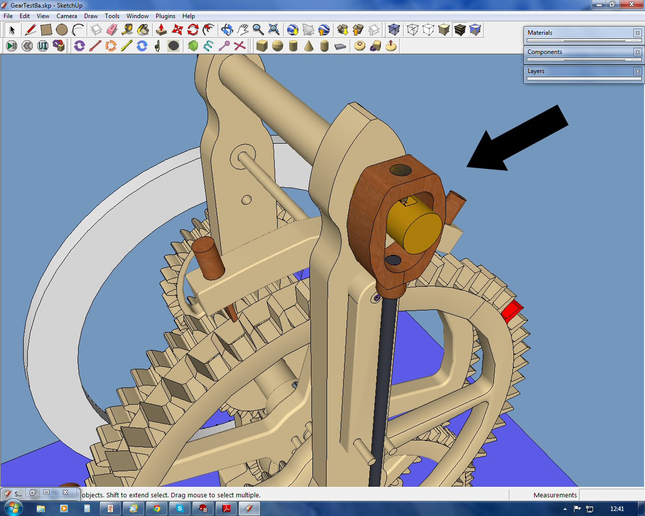
I'm building a clock originally designed as a wooden device by Brian Law (http://www.woodenclocks.co.uk/). The clock is driven by a motor on the gear on the lower left looking at the front of the clock. In the original design, this was a round box with a spring drive. The clock is regulated by a pendulum that operates the escapement, which , in turn, regulates the clock's rotation rate.
The thing is working pretty well right now, but there is one small problem. The pendulum's movement is controlled by an oscillator. By changing the oscillation rate, it should be possible to set the rate of movement of the whole thing so that it actually tells the time. The trouble is that the pendulum wobbles about it's pivot point (see arrow in screen shot.) This, in turn, causes the escapement to behave in a erratic way as well. My question: is there a way to anchor the pendulum's pivot more securely?
Any help would be appreciated,
Tom
Thanks, John,
I'm in the middle of building a model of a pendulum clock in SU8. I do have SU7 on my machine, but if I use it, I'd have to start over from scratch. I'll try turning off all the other plugins and see if that works. All these crashes are getting to be a bore.
Tom
@unknownuser said:
A cool trick is use SketchyPhysics "alone" inside the Plugin folder !
So just make a special "Plugin" folder for iself!So no incompatibilities with other plugins!
Hi Pilou,
How do you do this? Can SU have more than one Plugin file at the same time or do you give it a different name?
Thanks,
Tom
@unknownuser said:
A cool trick is use SketchyPhysics "alone" inside the Plugin folder !
So just make a special "Plugin" folder for iself!So no incompatibilities with other plugins!
Does anybody know what other plug-ins are incompatible with SP?
@ashscott said:
So you work with these things in real life?
No, I'm retired. I just saw a video on YouTube of these robots and decided one would make a good SP model. The company, Qineteq, is a British company with manufacturing in the USA as well. They sell robots to both the British and American militaries. A Google image search turns up a lot of pictures of the machines. There are also some cool videos on YouTube.
I don't have a joystick so I changed the clamp to keyboard control and I was able to work the machine quite well. Also I get the idea of the camera positions now. Thanks.
Oh, and the robot is the one on the right in the picture.
Thanks, Ash. I'll start snooping this afternoon.
Here's the Dragon Runner model: http://sketchup.google.com/3dwarehouse/details?mid=21145f3a959b5250e58ffa234975fda
By the way, here's what the real robot looks like.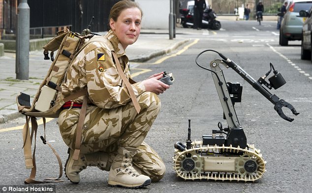
Hi Ash,
That model looks very cool. It's too bad you can't share it. I'd love to look under the bonnet. I've been working on a similar project of a bomb disposal robot(see other posts in this forum for photos of the real thing and some track problems.) Here's the model before the simulation. 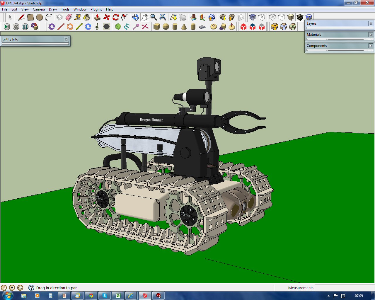 And this is it with the boom and arm partially extended.
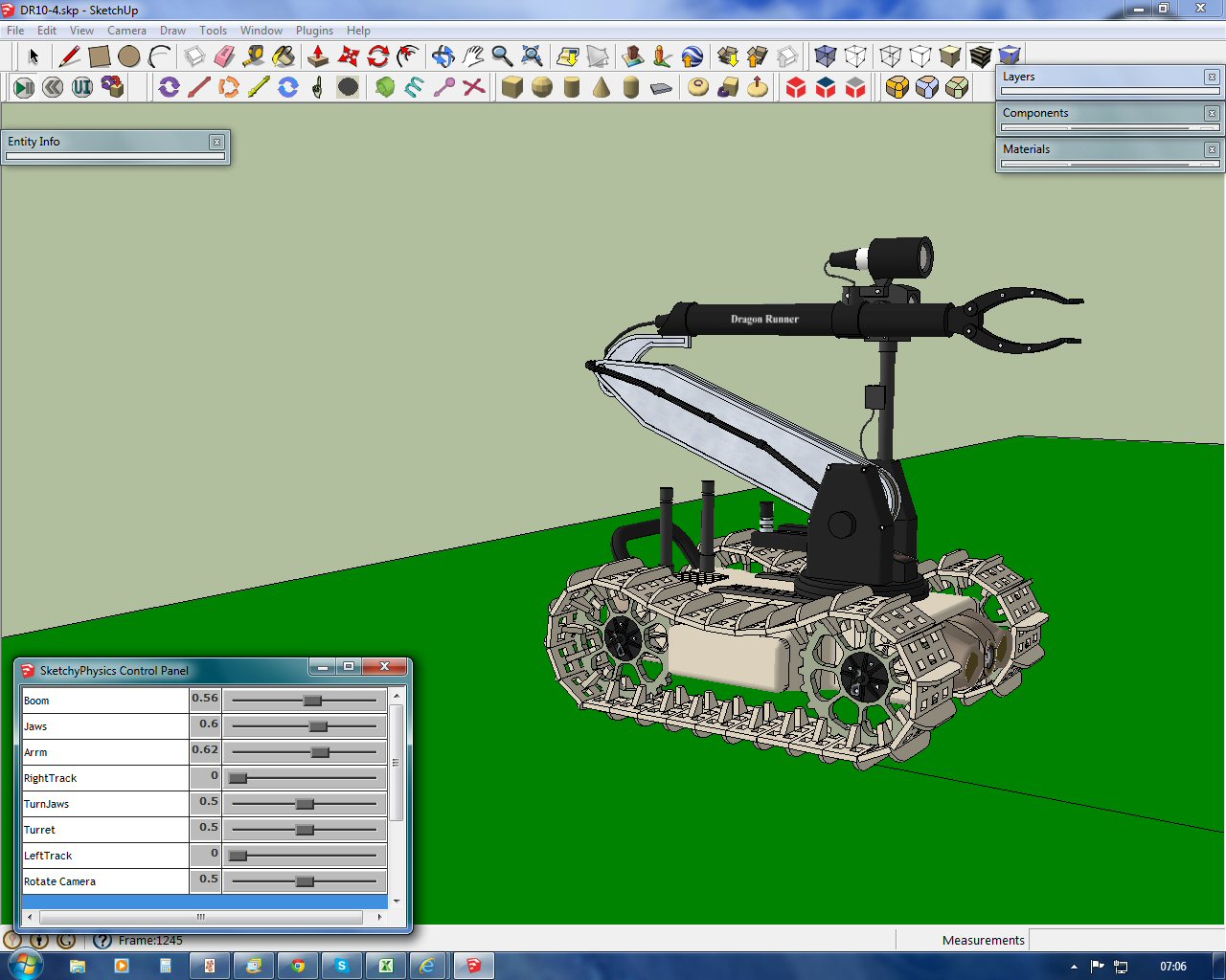
The base rotates, the boom raises and lowers, the arm extends and the jaws rotate and open/close. All of that works fine. An earlier wheeled version is in this video:
http://www.youtube.com/watch?v=ZY9pQ2mUSJM
The real robot has 3 cameras that the remote operator can use when manipulating the machine: one mounted on the arm, one in the front of the hull and one on the turret that pans and swivels up and down. I'd like to be able to switch between these cameras during the simulation just as the real operator would do. Is there a model in the 3DWH that has multiple cameras that I could study to incorporate this functionality in mine?
Any help would be much appreciated,
Tom
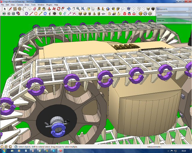 Hi mptak,
It's the hidden geometry in the track elements that is set to Box. These are the parts that are in contact with the floor.
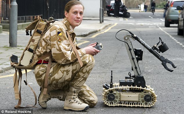 I've been working on an SU/SP model of a military bomb disposal robot called the Dragon Runner. This machine comes in several configurations, two of which are the wheeled and tracked versions.
http://www.youtube.com/watch?v=ZY9pQ2mUSJM
I've cracked the wheeled one and have made progress on the tracked one. I've spent hours on this forum and looked at a lot of working examples of tracked vehicles in the 3DWH. After all this, I have one problem and one question:
Problem - The model currently has one Slider control for each track so that it can be steered and the drive joints are motors. It seems to work just fine going in a straight line, but when I try to turn it, the left track gradually comes off the drive wheels. I can’t figure out why this is happening. Any ideas would be appreciated.
Question – Ultimately I’d like to control the tracks with the Lefty and Righty keys so that the model starts out stopped and can be driven and steered from the keyboard.
Thanks for any help,
Tom
http://sketchup.google.com/3dwarehouse/details?mid=eb44b2ad6f12cc68720db6663e814a6b
I Have a (tongue-in-cheek) suggestion for addition to the next version of SP: A new joint called "Grease".
Tom
First I drew the two spirals 180 degrees out of phase and superimposed them on a central cylinder. Then I selected the band on the cylinder between the two spirals. Next I selected the other band moved it away from the original cylinder and scaled it down to 90% in both horizontal directions and put it back into the original position. Using one side of each of the spirals, I built a box that fit the two curves. I made the box into a component and set the Shape to ConvexHull. I then copied the component 31 times and lined them up to make a 3D spiral.
I'm making some progress. The attached model rotates and slides, but now I need to figure out some keyboard controls for the simulation. This one is based on a working nut and bolt model by sofie9536:http://sketchup.google.com/3dwarehouse/details?mid=9910da9a33ee78c8c17e81e068e37f73&prevstart=0