That's not too bad, I never saw the upgrade price, just Buy Now price. Makes sense an upgrade would be cheaper.
Thanks,
That's not too bad, I never saw the upgrade price, just Buy Now price. Makes sense an upgrade would be cheaper.
Thanks,
Thank you so much! You all have been very helpful with everything. I wish I had more time than I do to play and experiment with the program to learn more faster.
I noticed that SketchUp 2016 is 64bit specific, I have 2015 pro and my upgrade license seems to have run out. Has anyone noticed a difference strong enough to make it worth dropping the money for 2016 to have the 64bit version? I assume that it makes calculations and rendering faster, anything else better? Since I am running 2015 Pro, I would hate to swap to 2016 without it, but am not so sure about spending another $700 or so on it right now.
I just wanted to say a quick thank you to everyone. While I have not been able to offset the runners as I wanted, I was able to rework the runner length, height and curve to achieve what I wanted, with out needed the offset.
Easier to draw, easier to build!
The hard part of the manifold drawing is complete and I can work with it now.
The ends are and lifter valley plate are all that I need now and they are easy.
The top plate is simply an adapter to let me run any type of induction setup that I want.
When I save it, I receive a message that states that there are problems, when I let it fix it the plenum is messed up. With the "problems" everything is solid and happy.
Thanks again!
I am truly sorry to keep posting about this dumb manifold project giving me fits.
But I have a challenge that even Follow Me and Keep, or the other extrusion ruby I downloaded aren't solving well.
My starting face is at 45 degrees, ending at 22.5 degrees. It is offset forward 15/32" and I raised the elevation of the ending point 1/2" to decrease the sharpness of the bends a bit into the flange.
Follow Me works the best but rotates the runner at the plenum end.
Follow Me and Keep keeps the runner profile vertical and ends up changing the runner size a bit.
The other one, just did weird things.
Anyone up for the challenge? The real challenge being to teach me how to do this so I can quit bugging the world about it? 
I have my desired path in this file, the runner surface to use on the flange. When the runner is Follow Me tool extrudes it to form the runner, it is great, but the end rotates a few degrees and is no longer straight like it was leaving the flange.
I would cheat and switch to round tube runners, but the bells to adapt round tubing to the ports in the flanges take up to much space to be feasible.
Thanks again for your help.. and enjoy! I know someone will do this in a couple of clicks half asleep, but it sure isn't me yet..
Thanks for the suggestion, I had had Follow Me and Keep at one point and lost it. Sadly I forgot where I acquired it from!
I just found it here though, as well as the Eneroth extruder to play with as well.
More to play with tonight! I am determined to get this manifold drawn. I found the perfect scrap aluminum to build the runners and plenum out of today if I can just get to a point where I am happy with the model!
One more question. I was attempting to have the runners offset forward on the left side, and aft on the right back. I used the Bezier Curve tool to draw the path that incorporated the elevation change like the previous test drawings, and added the fore and aft shift into it.
When it drew the tube along the path, the runner twisted at the plenum end, and was no longer parallel with the starting point. It's like it rotated along the path. Is it because I was attempting to curve it it through multiple directions? I never noticed it with round tube runners since rotation doesn't matter, but it became vexing with the rectangular runner.
I found an old manifold to get my true dimensions needed off of today and started the accurate drawing.
I pretty much did the same thing as the previous test, just set the runners a little different, and the plenum cuts in deeper.
I scaled up 100 times and this time I ended up with the same issue as before I scaled up and tried to split it.
I scaled up another 100 times and still can't get a clean split to remove the runner and plenum pieces.
I did get it to behave on that previous test version.
Once the split is completed, both pieces still show as solid, but once I double click on the pieces to delete, I lose the solidity of the plenum box this time.
More to play with I guess.
Thank you, I haven't played with scaling yet, I will tonight.
When you said you did the intersecting manually, do you mean you used the intersect options when you right click? Those have confused me some as I haven't seen what they actually do.
I should probably spend more time on You Tube looking for tutorial videos.
Thanks again for the suggestions though. And your picture that is attached gives me hope that what I am trying to do is possible!
Looks like I get to stay up playing with it some more tonight!
Hello,
I am attempting to trim intake runners against an intake plenum and have the portion of the runner that extends into the plenum removed, as well as the portion of the plenum wall that would be inside the runner removed.
When I use the solid trim tools, it sort of works and I can go back and delete the portions necessary, but the runner is no longer solid.
Is there an easier way to clean up the results other than going in and manually cleaning up all the geometry?
I have attached the project file to this as well for those that want to play with it.

I installed and played with the Bezier Curves tool, so far so good, it is certainly a lot easier than how I was making the paths. The paths may not match available tubing u-bend radius' to fabricate from, but it provides the visual concept well perfectly!
Thanks again for the guidance! My test manifold for tubing alignment using Bezier Curves attached to straight stubs.
Thanks, I will study it some. Part of my arc issue is trying to maintain a set radius, such as 3" of which mandrel bent tubing comes in so that I can cut the pie shapes out to weld together in order to get the final shape. In the drawing I try to stick to the known radius of bends that I can buy and work with.
I think with a reference point to indicate the radius, these curves may work nicely as long as the face will always be perpendicular to the starting and ending points.
Thanks!
Box, essentially I want to draw exhaust headers and intake manifolds where the tubing from the intake/exhaust ports bends, and sweeps around to mate up with it's final destination.
Say for instance the exhaust port is at a 45 degree angle facing down. The tube would need to start at that angle to match the port, sweep down, back, and around obstructions. I have a hard time setting up the path made of arcs cut from a circle to get my distances, angles, and offsets correct in order to make the path for the Follow Me tool work with.
The last time I played with it, I sectioned a circle into 8 pieces to make 45 degree arcs, then squared them up and added very short lines to get the faces to end at the correct angles. I could copy and rotate that well enough and the tubing drawing started coming out square and true to my flange drawings. I did notice that If I used two different pieces of the cut up circle, they were not exactly the same though and to just copy and past the one I was happy with instead of moving the circle sections around.
They sure are!!!!!!!! LOL the hard part I have found is lining up the rotation tool at the end of each arc segment that is cut and linked from a circle with the radius needed to represent the bends that would be used. I think I will play with the perpendicular shapes tool that I have and see if I can add a shape to use as the rotation tool reference on the line segment itself then I can cut and trim the line segments as needed and rotate into shape.
I should probably sleep more, but the bug is biting me again now that I am building up a couple of projects and want to 3D model certain aspects first.
@dave r said:
Looks good. Make sure you have all front faces out. The first image shows the web and hub properly oriented but the outer rim reversed. It looks like all faces are versed in the second and third images.
I don't know about reversing faces, but I was wondering why when I worked with them some were grey and some were white.
The first one I made separate pieces and worked them all together.
The second one I started from a "block" with the sheave profile on the outside edge before using the follow me on a circular path. Then used push pull a lot to machine the web and hub into it.
The entire time it was grey, how do I reverse faces so that white is shown?
Something more to play with tonight, sweet!!!!!! I was playing with tubes again last night, I like headers and intakes, but was still having a hard time with creating the path to follow through multiple planes accurately in order to achieve the twists and bends I desire.
edit SKIP THAT!!! WOOHOO!!!.. I just figured out how to reverse the faces! Thanks for the heads up about that!!!!!!!!! It's fun being surrounded by loads of people with for more knowledge and experience to feed off of!
I played around last night and have a better handle on the Follow Me tool now. Not perfect, but that just means more nights of playing with it to learn more! 
Anyway,
Here is what I whipped up before bed.

I forgot to setup the first V pulley for a higher number of segments before creating the circle.


Overall I am happy with them now, I can create a drawing that will work for the pulley manufacturer to work with.
Thanks for the knowledge nudge!
Thanks, I will play with it some tonight. So far the Follow Me tool and I haven't gotten along, but I was trying to do intake runners that shifted around a bit and ended up with non-perpendicular faces to the end points when finished.
Hello,
I have some experience with SketchUp Pro, but not enough to venture into my next desire easily.
I am wanting to learn to draw pulleys. Both V and serpentine design. My intent is to draw them and export the files to a manufacturer to cut for me.
Has anyone played with pulley drawing before that would have some tips to simplify the process, or at least the learning curve involved?
Thanks,
Ryan

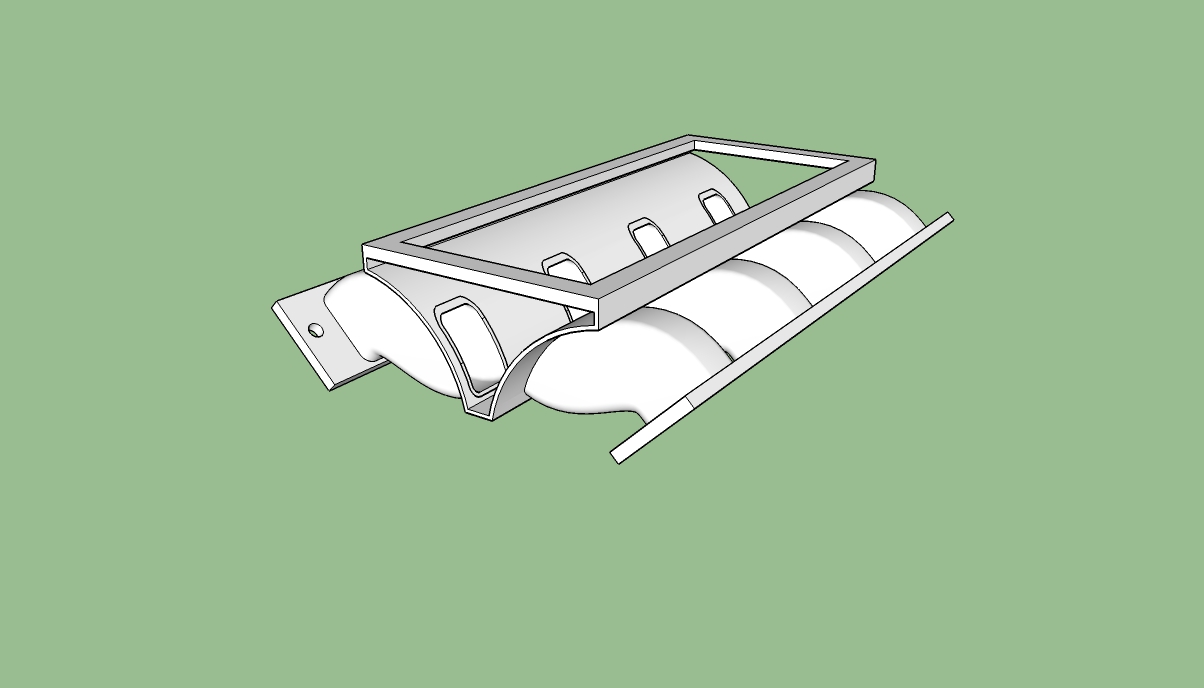
I wanted to put a big thank you to everyone again. This is not a drawing to true dimension of the lower manifold for my engine project, but rather a conceptual rendering. My core block and heads are still on the boat and I am too impatient to wait for them to arrive to measure and go to that detail with the design.
But, this was an EXCELLENT instructional project to achieve my goals for the design.
I still need to add the injectors and design the plenum for the proper volume and blower mounting, but that part is easy compared to the runners!
Thanks again, here is the model rendered out showing the plumbing and base plate in place.
Thanks again,
I will study these tutorials and work on my original path some more to get the runner setup and lay outs correct. I am essentially trying to get the intake runners on my engine to clear each other as if you meshed your fingers together, but the intake ports are wider than the cylinder off set, so the runners need to be shifted towards the front of the engine on the passenger side, and rear on the drivers. Fortunately if I can draw one runner correctly then the rotate, copy/paste, repeat method works perfectly to finish the other 7 for me.
I have a path that is very close to what I am aiming for, just needs the straight segments at the ends, and to have the angles and arcs cleaned up a little. I will work on that some more and post is up to show when I finish, or hit a wall... again.
Thanks again everyone. I really appreciate your patience and guidance with this. I am to stubborn to give up, and will kill myself trying! LOL
I found an easy, though not perfect work around that works for what I need after seeing the diagrams where the arc does not start square to the surface.
I moved the arc up 1/16" and drew a straight line to weld to the arc, then did the same at the tail end to give a square end.
This isn't the perfect solution, but works well enough for my needs to get the follow me tool working "correctly".
Now drawing all the arcs and lining them up to produce the multiple curves and offsets that I need are proving to be a huge challenge.
I am used to prototyping with raw material, rather than a digital rendering. So moving my mental image onto the screen without being able to grab a physical object and manipulate it into the position that I need has been a huge learning curve!
I did manage to work up a nice timber frame structure and cabinet setup, but the tube bending thing has really thrown the gauntlet at me!
Great fun though!
Thanks again to everyone for all the advice, help and testing of the drawings on your end.