Follow Me and Keep / Weld help
-

Hello,
Since I have been lead here a couple times by Phil on the SU help forum, I figured I would just say hi, and post my questions here to see how the results fair.
I have downloaded the Follow Me and Make plug-in as well as Weld in an effort to make accurate, and clean intake runner tubing for an engine project I am going to build for myself.
I need help with the procedures to use these extensions though.
I am not getting the two plug-ins to work consistently and when I do, I don't know what I did differently that made them happy.
How do I use the Follow Me and Keep extension? I watched the video on Vimeo and thought I had it. It worked once, then not again until I made a separate test model last night. Then again no dice this morning.
The same issue with Weld. It seems simple as pie, selects your line/arc segments, weld them and done. But the weld is not "taking", and when I select the new welded line, it is still a bunch of segments.
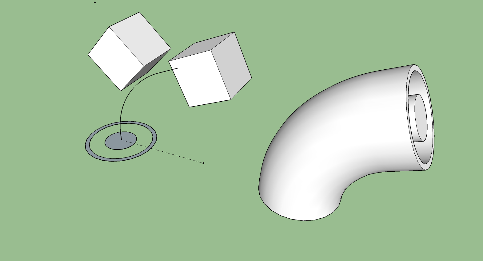
In the file I have attached, there are three arcs, and a straight line. I managed to weld the first two segments near the profile shapes I am trying to extrude, but the other two would not weld.
I also never managed to make the FAK extension work in this model either. Is it a SU 2014 issue, or am I just way to new and missing something?
The cubes are just in the file for face references to set the arc and protractor tools too since I haven't figured out how to make them perpendicular to an end point without a face reference yet.
-
Hello Ryan,
I'm not sure why you were having issues with Weld not welding the portions of the path together. It worked just fine for me as you can see in the attached file. There are two common reasons for Weld to fail, though. The first is gaps between the edges being welded. The other is when there is a branch which isn't too uncommon when putting arcs and lines together unless you do it with care. I found neither problem in your model, though.
As for FAK. I don't see any reason to use it for this model. I used the native Follow Me without problem. You do want to be careful because you're working at a fairly small size and you could have tiny gaps forming because SketchUp won't make very small faces. These happen when line segments are very short. Again, I didn't see any issues but it could happen if you have more small parts to draw. The solution is to work at a larger scale and scale down after doing whatever it is that would create the tiny faces.
-
Thanks Dave,
I am trying to use the FAK plug in because when I use the Follow Me tool the ends don't come out at the correct angle. They seem to be a couple of degrees off.
The starting point face rotates down leaving a gap at the far side of the arc, and recessing the near side down into the the component below. The ending face ends up falling short of the angle for the desired plane as well.
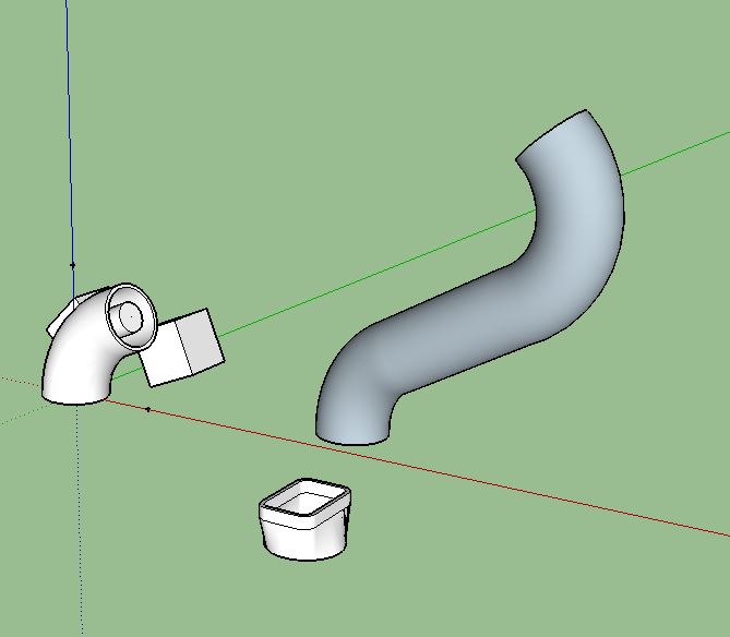
The model shown is just a quick testing example. The real model I am working on is a series of arcs and lines that rotate the path down, forward, back a little, then up to form an offset to clear the runner from the opposing cylinder head.
My interest in FAK is that it leaves the starting and ending surfaces at the correct angle to continue building from for the rest of the intake manifold.
I did get the weld to work by exiting out of SU, then going back in. But the FAK never did work. Maybe I need to reinstall the 2013 and try with it.
Thanks for testing it though, it's nice to know that my models are right, just something screwy elsewhere is going on!
-
Something else you need to be aware of is Purging.
When you delete things from a file Sketchup still retains them in the file incase you want to use them again. They add to the file size and as your model gets bigger and more complex they are a drain on resources and can slow things down, not to mention make it difficult to upload or send the files.
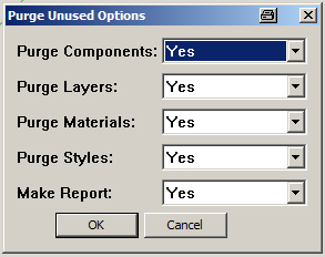
As you see in the attachment I brought back some deleted items. I purged them and resaved and it halved the file size even after doing the followme on your shape.To purge a model go Window/Model info/Statistics and click purge unused.
-
@rcvowell said:
I am trying to use the FAK plug in because when I use the Follow Me tool the ends don't come out at the correct angle. They seem to be a couple of degrees off.
The angle of the last segment is the one which defines the angle of the end face...
@box said:
To purge a model go Window/Model info/Statistics and click purge unused.
And if you want more control which parts of the model are purged, you can use TIGs plugin PurgeAll...
-
Thanks!
Do you use the arc tool to draw your arcs, or as in the example you provided, do you cut sections from a circle.
Can the number of segments be set for arcs to help insure that they end square to the desired direction?
Also thanks for the heads up on the purging. I am erasing a ton as I go and try to learn new things, time to start dumping my trials and errors!
-
@rcvowell said:
Do you use the arc tool to draw your arcs, or as in the example you provided, do you cut sections from a circle.
If you want the ends of the arc to be at 90° to each other, you need to use the Circle tool.
@rcvowell said:
Can the number of segments be set for arcs to help insure that they end square to the desired direction?
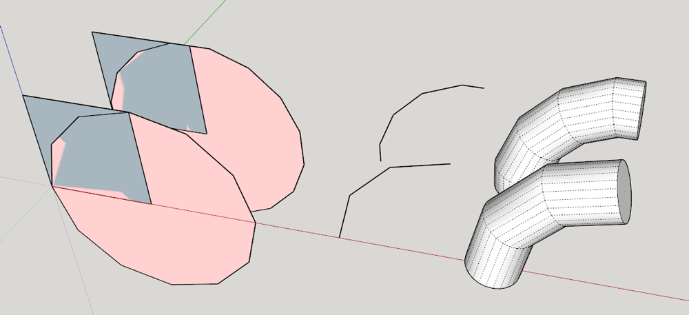
No. The first and last segments in the arc will always be at an angle other than 90°. Actually, there would be one point where the segments would be square to each other but setting the arc reliably so they are is a challenge. If you drew the arc between diagonally opposite corners of a square, you would find the radius of the arc is slightly less than the length of the sides of the square.
-
I found an easy, though not perfect work around that works for what I need after seeing the diagrams where the arc does not start square to the surface.
I moved the arc up 1/16" and drew a straight line to weld to the arc, then did the same at the tail end to give a square end.
This isn't the perfect solution, but works well enough for my needs to get the follow me tool working "correctly".
Now drawing all the arcs and lining them up to produce the multiple curves and offsets that I need are proving to be a huge challenge.
I am used to prototyping with raw material, rather than a digital rendering. So moving my mental image onto the screen without being able to grab a physical object and manipulate it into the position that I need has been a huge learning curve!
I did manage to work up a nice timber frame structure and cabinet setup, but the tube bending thing has really thrown the gauntlet at me!
Great fun though!
Thanks again to everyone for all the advice, help and testing of the drawings on your end.
-
Adding segments at the ends of an arc can be a useful way to achieve what you're after. In some cases that might provide a more realistic pipe anyway.
As for drawing the arcs, if they are to be in a single plane, draw a large rectangle and work on it. That would be much like working with real pipe on the bench. Then delete it when you've finished. If your curve will be in 3D, draw on a cube or other shape.
Although not pipe, I did a tutorial video showing drawing a curved path in 3D for Follow Me. It might give you some ideas.

-
When you want a complex path, draw it as straight lines and then add the arcs to the create the bends.
The built in inferencing of sketchup helps you create arcs that join smoothy. When you use the arc tool take note of it turning pink when you select the second point then it turns pink again when you get the arc to a natural curve. Also, the arc tool will continue the curve when you start a second curve from the end of the first, it turns green, you can move around and simply double click to place the curve and it will be a smooth transition.
Here's a short vid I did some time back to show making a path, you see the pink inference on the first curve.
[screenr:26o83wrn]LALH[/screenr:26o83wrn]
-
Thanks again,
I will study these tutorials and work on my original path some more to get the runner setup and lay outs correct. I am essentially trying to get the intake runners on my engine to clear each other as if you meshed your fingers together, but the intake ports are wider than the cylinder off set, so the runners need to be shifted towards the front of the engine on the passenger side, and rear on the drivers. Fortunately if I can draw one runner correctly then the rotate, copy/paste, repeat method works perfectly to finish the other 7 for me.
I have a path that is very close to what I am aiming for, just needs the straight segments at the ends, and to have the angles and arcs cleaned up a little. I will work on that some more and post is up to show when I finish, or hit a wall... again.
Thanks again everyone. I really appreciate your patience and guidance with this. I am to stubborn to give up, and will kill myself trying! LOL
-

I wanted to put a big thank you to everyone again. This is not a drawing to true dimension of the lower manifold for my engine project, but rather a conceptual rendering. My core block and heads are still on the boat and I am too impatient to wait for them to arrive to measure and go to that detail with the design.
But, this was an EXCELLENT instructional project to achieve my goals for the design.
I still need to add the injectors and design the plenum for the proper volume and blower mounting, but that part is easy compared to the runners!
Thanks again, here is the model rendered out showing the plumbing and base plate in place.
Hello! It looks like you're interested in this conversation, but you don't have an account yet.
Getting fed up of having to scroll through the same posts each visit? When you register for an account, you'll always come back to exactly where you were before, and choose to be notified of new replies (either via email, or push notification). You'll also be able to save bookmarks and upvote posts to show your appreciation to other community members.
With your input, this post could be even better 💗
Register Login


Advertisement