sketchucation logo sketchucation
    • Login
    1. Home
    2. pcmoor
    3. Posts
    Oops, your profile's looking a bit empty! To help us tailor your experience, please fill in key details like your SketchUp version, skill level, operating system, and more. Update and save your info on your profile page today!
    🫛 Lightbeans Update | Metallic and Roughness auto-applied in SketchUp 2025+ Download
    P
    Offline
    • Profile
    • Following 0
    • Followers 0
    • Topics 1
    • Posts 378
    • Groups 1

    Posts

    Recent Best Controversial
    • RE: Can dynamic Components be scaled from the center of part?

      Hi

      Yes, can when creating by positioning the axis at the centre or position you want. You can also move or place the axis afterwards by opening the component, right clicking the axis, (context menu) and picking place. A warning will ensue but if should be okay provided you have not already place position attributes formulas within the component already (if I change at a later date I check that X,Y,Z have no formulas or redo them to suit)

      Philip


      Capture.JPG


      Capture2.JPG

      posted in Dynamic Components
      P
      pcmoor
    • RE: Not sure why my dc does this axis

      Hi Brian,

      Initially posted a reply suggesting you place it into a wrapper component to protect your work, which would work, however realised more to this project.. added a review of your idea with some different code

      aside to this uploaded an array concept without using copies of rows for consideration for other projects

      hope it helps
      Philip


      array.skp


      fibb.skp

      posted in Dynamic Components
      P
      pcmoor
    • Mitre Box

      Hi

      one of the most agonising early tasks as an apprentice carpenter was figuring out and cutting those mitred moulds. we had to make our own mitre boxes then, no drop saws. Eventually one was able to mitre and scribe without a guide.

      So I figured I make a virtual mitre box to build dynamic mouldings
      attached to share.....

      Philip


      moulding template.skp

      posted in Woodworking
      P
      pcmoor
    • RE: Dynamic Component of a bi-fold door

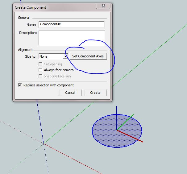
      Start simple, create a rectangle, make it a component, "door" later you can replace it with any other component

      copy the door to make number required

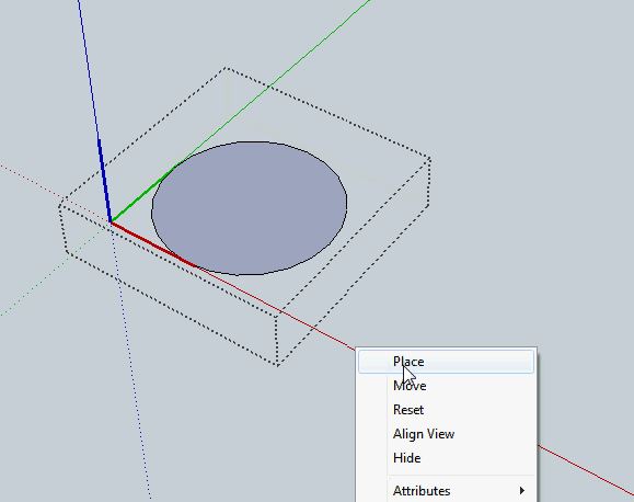
      make all a component, then enter the component, make next set of doors a component but change the axis so that it is opposite to the parent

      do so until you reach last door, then in this case check to see if opposite if not then right click the axis when inside this door component and change

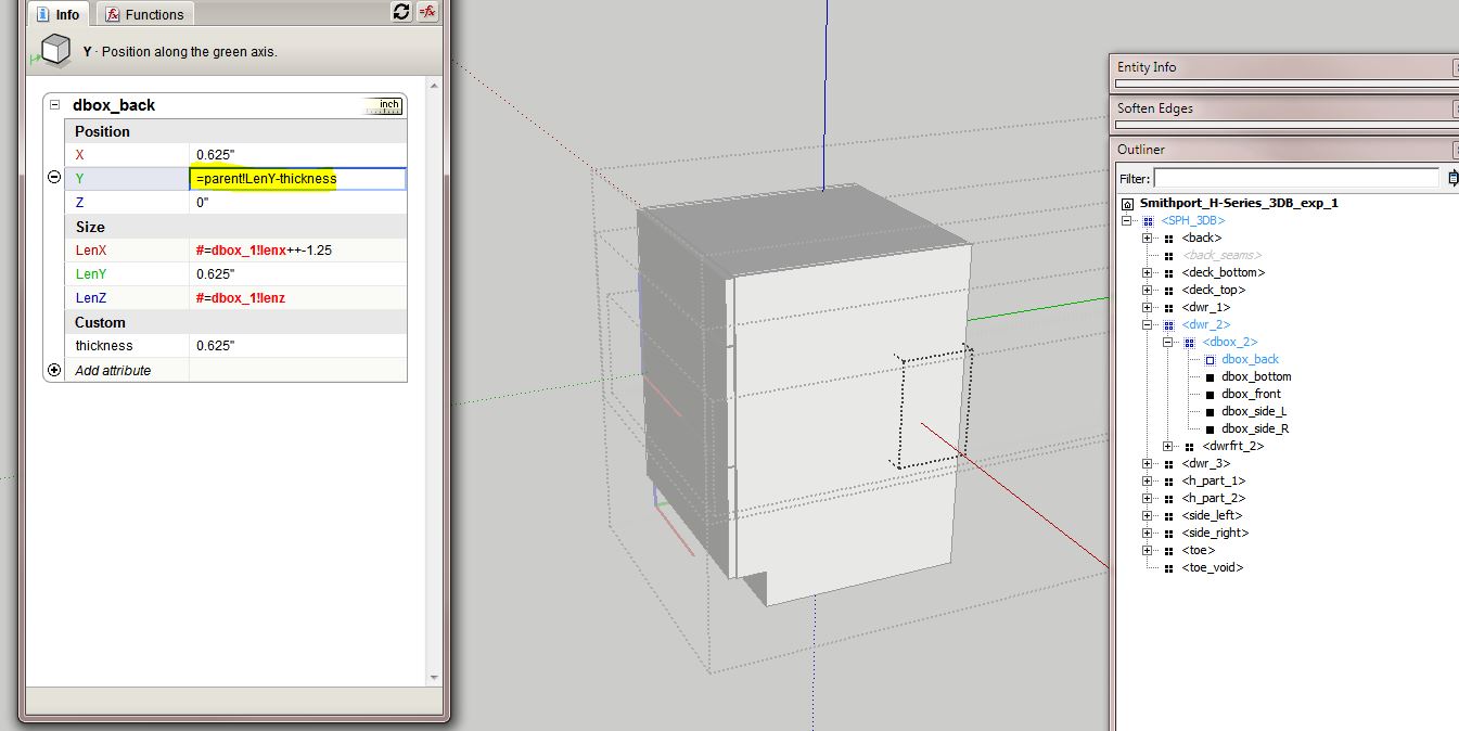
      build formulas as shown

      rotate about Z, opposite and reversed (90 x 2 = 180) x -1
      I used the generic parent as the reference rather than component1 as suggested by Dave and others, etc, so easy to copy through.

      the rest are always opposite to component 2, so -parent!rotz works

      always check as you build, so see that it works...

      Then you can modify the door component. however its important you stay within the initial dimensions of the door boundary box. To increase its size, use scale tool on the whole (component1)

      So add the size changes to component 1, the children will follow, its not wise to have the children tell the parents what to do. Unless its necessary.


      keep it simple


      ![make a "door" component and copy 3 times](/uploads/imported_attachments/lcN7_Capture2.JPG "make a "door" component and copy 3 times")


      make the four doors in to component#1


      enter the this component and make the next 3 into component#2, change axis to other side


      and then enter component#2, make component#3 of the last two doors


      enter the final door component and check axis position


      ![we are considering rotation about Z, direct reference to"RotZ" as using negative](/uploads/imported_attachments/eQ9T_Capture7.JPG "we are considering rotation about Z, direct reference to"RotZ" as using negative")


      ![the second set needs to swing opposite first set, so "-" and 180degs =2x90](/uploads/imported_attachments/Rirq_Capture8.JPG "the second set needs to swing opposite first set, so "-" and 180degs =2x90")


      from then on opposites... use the outliner as a way of selecting the embeded components


      make sure you  have the final door


      now you can pushpull the door height


      add a bit of detail but (color) keep within the lines, or within the boundary of the door

      posted in Dynamic Components
      P
      pcmoor
    • RE: Push several drillings- holes at once

      Hi

      a DC component is another method, place, size, copy array multiply then when happy....explode..3 times

      one for the group
      one to cut back faces
      at last another to remove the groups and smaller components

      this can be achieved via right click, select context menu "explode"
      note afterwards it pays to purge the drawing as unused components remain attached to the file.

      Something else to add to the tool box?..

      Philip


      Hole Cutter 2.skp

      posted in Woodworking
      P
      pcmoor
    • RE: Variable Rabbet and Dado Depth/Width for a Dynamic Component

      an idea...

      to make the cut-list see it as one piece, explode the internal components or groups, leaving the outside component with you main attributes, then cut-list will take-off the item correctly. Then if later you required to modify, swap it with a saved component in your files.

      These components need to be set up so as to reference the options/attributes left behind on your internally-exploded component. Then they will update. Use the generic parent! in front of the attribute you are trying to change, not a specific parent name.

      In DC folder you might have "door","window" and "xx_door","xx_window" where the latter are already contained in the former, and can be swapped in the model. Typical the attributes like =parent!LenX will be red in these xx_ children looking for adoption

      why "xx_"? well I am sure a well-meaning ruby coder could make a script to attach to the cut-list menu, that could explode the a selection or all the entities with this prefix or similar. Plus even go one step further and delete the internal geometry, ready for printing?

      I did also consider "shell", but then cut-list reports on the generic shell name, plus the inners have to be solids

      Philip

      posted in Dynamic Components
      P
      pcmoor
    • RE: Need help on a panel door

      Cheers Mike,

      it works, just need to hide the joins (double click the offending surface, right click, hide)
      I am glad you didn't give up...
      your model is completed..I'm still playing around with some ideas...

      I added formulas to the mould I made which allows change in degrees, added options to pick scale or fixed length (thanks to "eselick".... "Scale AND keyed in values for component size")

      Philip


      stage 3 ...refinements


      mould template.skp

      posted in Dynamic Components
      P
      pcmoor
    • RE: Need help on a panel door

      had a quick look @ cutlist

      I note that my picture frame produces 4 lengths (middle) and 8 ends (4 left,4 right), the middles are short points to the mitre ends

      if I open a moulding and explode the 3 groups then I can get a single entity on the list

      (this maybe the foundation to a ruby script,,,"explode internal entities", the coders can make)

      posted in Dynamic Components
      P
      pcmoor
    • RE: Need help on a panel door

      Hi again

      with regards to building the mitred moulding
      I hide the the share lines and delete the the internal surfaces
      Then change the axis so as make minimum need for formulas,

      the sizes of the mitres are trapped, the section of the length is also trapped, only movement is along x-axis

      the scale tool is incorporated for easy size change for other projects

      with regards to "cut-list" I did not know it was part of the criteria so I've downloaded it and will try to figure it out

      cheers


      hide shared outlines, delete shared faces


      make group with axis placed as shown, click into lenX,LenY,LenZ and place = before the value
this will stop the mitre from distorting


      middle, place axis along same line, make LenY,LenZ fixed


      right, same as per left


      with the groups placed together make them a component with axis placed as per left group, this then minimizes the need for complex positions, only need to consider changes in the X direction of the groups


      now consider the relationships with the groups for positions along the x-axis


      restricted scaling of the component (this is done for reuse for other projects


      add a relation between lenX of middle and full length of object


      pciture frame.skp

      posted in Dynamic Components
      P
      pcmoor
    • RE: Need help on a panel door

      A nice detailed door

      the first step is to identify components which we can reuse, these are the back board, rail, style and mould.
      the board is quite simple and probably best suited as the reference to position the other components

      now split the rail into 3 simple shapes and make them groups not components, you can see the stile is similar so it can be a modified rail.

      the mould is spilt into three, the mitres and the length between

      step 2 to come soon...


      Step 1: split the object into simple shapes

      posted in Dynamic Components
      P
      pcmoor
    • RE: Drawer box depth won't change along with cabinet depth

      Hi Eric

      you have used the same groups for drawers 2 & 3, if you click into the attributes of say drawer 2 side, you will find that it is red , it refers to drawer 1, You need to change the reference of the group, if they were components then you would have to make them unique.

      since its most likely you want to reuse certain elements again rather than making each unique or updating the reference, replace the reference with parent! instead of the parent name, then the "child" refers to any parent rather than any specific one.

      This is they important when you want to swap components, say a door type, or knob.

      Cheers
      Philip


      Capture.JPG

      posted in Dynamic Components
      P
      pcmoor
    • RE: Controlling more than X/Y/Z and height/width/depth

      Hi

      Since you want to create an object that maintains two ends with variable distance between then split into four as you have drawn, the half cylinder ends as per attachment, the trick is to build cutting holes top, bottom and side, hide any lines not needed to be seen (outline of hole), add outlines or faces (e1,e2 you can delete these for your project) as required. See my models on warehouse...cylinder, pcmoor

      the rectangle sides should be no problem, hide the lines at the joins. The position of components can be tricky, but i let you give it ago, let us know if you need further help

      Cheers
      Philip


      half cylinder.skp

      posted in Dynamic Components
      P
      pcmoor
    • RE: Changes in X, Y, and Z always cause changes in X

      Could you upload the components so we can look at the problem?

      posted in Dynamic Components
      P
      pcmoor
    • RE: SLOW COMPONENT EDITING / PURGING

      Could try fixing model, via Model info, statistics...next to purge... ?

      posted in Newbie Forum
      P
      pcmoor
    • RE: DC independent interactions

      Hi Again

      Figured it out, place the two doors (with separate "on click") within a component, have the main door reference the wrapper or parent, thus if you pick the small door it rotates or the larger door the whole lot rotates

      Cheers


      gate3.skp

      posted in Dynamic Components
      P
      pcmoor
    • RE: DC independent interactions

      This example uses a different trigger point, red opens main gate, green small

      gates move independant
      cheers
      Philip


      gate2.skp

      posted in Dynamic Components
      P
      pcmoor
    • RE: Cut Openings On Both Sides of Roof Pitch

      Hi

      one method is build various cutting planes within a wrapper component, thus activating them and leaving other embedded objects after exploding

      note that the wrapper has its own cutting plane, the axis is also placed for ease of use

      However the outline of the existing edge is left behind (the ridge in this case)

      Philip


      insert @ ridge line then explode

      posted in SketchUp Discussions
      P
      pcmoor
    • RE: HUGE problem with section slice groups !!!

      I did something similar,how about using the windows back-up files, save what you have to a thumb drive or disc, then return the documents to a previous saved backup

      posted in SketchUp Discussions
      P
      pcmoor
    • RE: Dynamic Door Cut Hole

      Hi

      By placing a component with hole cut both sides and a rim within a component wrapper one can place the door then explode the first wrapper which in turn activates both hole cutters

      attached solution which works after exploding, moreover have a look at the window opening for double leaf in my spot on the warehouse (pcmoor)

      updated opening to have size options

      cheers
      Philip


      insert bottom left, right click, explode

      posted in Dynamic Components
      P
      pcmoor
    • RE: DC independent interactions

      Hi

      All objects should be contained within the component you require to move. Have one animation that triggers the others, this is top down coding.
      By placing the rotation in a separate variable, able to work with finer degree changes.

      can make the actions follow on, but not independent

      Philip


      gate.skp

      posted in Dynamic Components
      P
      pcmoor
    • 1 / 1