sketchucation logo sketchucation
    • Login
    1. Home
    2. johnwmcc
    3. Posts
    ⌛ Sale Ending | 30% Off Profile Builder 4 ends 30th September
    J
    Offline
    • Profile
    • Following 0
    • Followers 0
    • Topics 18
    • Posts 105
    • Groups 2

    Posts

    Recent Best Controversial
    • RE: PointTool for Mac

      Just downloaded PointTool_1.2, using SU 2016 on iMac El Capitan, with autoinstall from the SketchUcation plugin store.

      Works fine as installed automatically, but puts Draw Points on the Extensions menu (formerly Plugins). I wanted to put it on the Draw menu, so changed one line in this part (sorry, don't have line numbers in my Text Editor)

      ` unless file_loaded?(FILE)
      file_loaded(FILE)
      $submenu ? (organizer = $submenu) : (organizer = UI.menu("Plugins"))
      organizer.add_item("Draw points"){ pointtool }

      p=Sketchup.find_support_file("Plugins")
      cmd = UI::Command.new("Draw points"){ pointtool }
      cmd.large_icon = cmd.small_icon = File.join(p, "PointTool", "PointTool.png")
      cmd.tooltip = cmd.status_bar_text = "Draw some points"
      UI::Toolbar.new("Point Tool").add_item cmd
      

      end`

      I changed just part of this line from:

      $submenu ? (organizer = $submenu) : (organizer = UI.menu("Plugins"))

      to

      $submenu ? (organizer = $submenu) : (organizer = UI.menu("Draw"))

      but now the plugin errors on loading. And still errors if I change the line back to have "Plugins" as in the original.

      Any thoughts on why this is happening, and how I could get it to load in the Draw menu?

      Of course I can (and shortly will) add a shortcut (probably Shift P) but I don't understand why this simple change stops the plugin working. I was using the built in Mac TextEdit.app which I assumed did what it says on the tin, like Notepad on Windows - or is it more like WordPad, and adding non-text characters to the file when saved?

      John McC

      posted in Plugins
      J
      johnwmcc
    • RE: [Plugin] PipeAlongPath

      I find this plugin very useful to draw scaffolding poles when designing amateur theatre sets using scaffolding as part of the structure. I've reset (in the code) the default sizes, and options, to suit my use.

      I'd also very much like to have the plugin create a component, rather than a group, and to orient the component axis along the direction of the first line segment in the path. Would that be difficult?

      I don't think my own SU Ruby skills are quite up to this, though I may well have a go - I might to able to code for component creation, but have no idea how to set the component axes in Ruby.

      posted in Plugins
      J
      johnwmcc
    • RE: Returning a value from a Class method

      @tig said:

      :shock:
      May I inject a pause, for reflection...
      If you explained [in words - NOT code] what it is you are trying to do, then we might better advise you...
      My own scripts do many convoluted things, but I have never seen the necessity to write a whole new 'Point' class to do something...
      I am sure that whatever it is you plan to do is quite possible, and probably considerably less complicated than you have so far contrived it to be... 😉

      Happy New Year...
      ☀

      TIG, a very helpful pause - I do get carried away, and I do tend sometimes to over-complicate! Your post crossed with my reply to Jim.

      I want to be able to draw frames for woodwork construction (mainly for our local amateur theatre stage scenery), using standard sizes of timber. Here's an example:

      Double window flat.jpg

      I have a working program (see last reply to Jim) which does this for rectangular timber. I'm trying to extend it to work with non-rectangular profile timber, and instead of PushPulling to length, to FollowMe round a selected path.

      In parallel with this aim, I'm also trying to teach myself better coding in Ruby, in particular, using objects with methods - IF it turns out to be appropriate (it may not, in this instance, as you rightly point out - but I did enjoy trying, anyway!)

      The drawing process in SU is:

      1. Use a Right Click to select the (nominal) timber size you want to use from a menu, or specify an actual custom size. Nominal sizes are 1/8th inch (3mm) or 1/4 inch (6mm) larger than the finished size. Remember the choice during the SU session, or until it is changed again.

      2. Pick a point, optionally on a face, optionally with an axis locked to X, Y, or Z_AXIS (toggle selected by cursor key). The timber's long axis (normal to its cross sectional profile) will be along the face normal if a face was picked, or the pre-selected axis if one was locked, or otherwise the Z_AXIS.

      3. Move or drag the mouse round the point, to set the direction of the timber profile with width horizontal or vertical, in any of four quadrants around the point. *If the camera view is looking 'down' the face normal or axis lock, then change the rotation so it still goes the right way round on screen, even though it is 'looking' at the 'back' of the face or axis.

      4. Use the TAB key to cycle the flip state of the profile (only useful for non-rectangular profiles, the next development that I'm trying to make). It can be flipped along its X, Y, or both X and Y directions, or restored to original.

      5. Click again or release the mouse button after dragging to fix the rotation, orientation and flip state of the cross section.

      6. Give a name to the component about to be created.

      7. Drag the mouse, or click again, with inferencing, or type a length in the VCB, to determine the length of timber to draw and create it as a component with its origin at the originally picked corner, and the component axes aligned with its width, thickness and length.

      8. For the drawn piece of timber, record its length and cross-section size and name in the ComponentInstance and its nominal or actual cross section in its ComponentDefinition.

      9. Return the tool to its original state, ready to pick again and draw another piece, usually though not necessarily picking on a corner, edge, or face of any previously drawn piece of timber, or another object.

      Ideally, you should be able to flip the cross section before or after the component is drawn, until the tool is next activated.

      [NOTE: * I added this bit about the camera viewpoint in a revision of the post]

      I hope that make the overall purpose clear.

      I've been fairly clear all along WHAT I wanted to do. The bits I've had most trouble with are HOW to do that in code, since I'm still not very familiar with Ruby, in particular how it handles arrays.

      I frequently get both the syntax and the semantics wrong - either can't get something to work at all, or it doesn't do what I expected it would, so I've experimented a lot, and usually get somewhere useful in the end. But I suspect that much of my code is horrible! I was trying both to simplify it, and learn about object-based programming in Ruby (which I understand in principle, and have done before in Visual Basic for Applications in MS Word, Access and to a small degree in Excel), and to a very limited extend in PHP.

      But all have been self-taught, or learnt from books and code examples on the Internet, with help from forums like this one (or similar for other languages).

      posted in Developers' Forum
      J
      johnwmcc
    • RE: Returning a value from a Class method

      That's cracked it! At last, the @profile_pointsH and @profile_pointsV have separate contents.

      And in retrospect, I can see why this works. Though not quite so sure (yet anyway) why the original PointsArray didn't.

      Thank you so much.

      Now I can get on with making the rest of it work again - I've had almost all the parts working at one time or another, but not using PointsArray - except for this last part, of getting the rotation and flipping to work together - one or the other but never both.

      posted in Developers' Forum
      J
      johnwmcc
    • RE: Returning a value from a Class method

      Have now put a simplified but non-erroring partially working copy of draw_framing.rb and changelog.txt on GitHub as v0.7.2.2 at

      Link Preview Image
      Commits · johnwmcc/draw_framing

      Sketchup ruby to draw timber framing in standard UK softwood sizes - Commits · johnwmcc/draw_framing

      favicon

      GitHub (github.com)

      I've also attached an installable .rbz file to this post. If you install that, you'll get the other needed files to make the draw_framing.rb code work - icon files, etc - and also some earlier versions copied into Plugins, but not loading.

      Run it inside Ruby console in SketchUp to see the behaviour I'm trying to fix - the V and H profiles always move together - V is drawn in 3px wide orange and H is 1px black.

      Mouse movement should (but doesn't) rotate the profile smoothly round the first pick point changing profile rotation quadrant, and orientation (width horizontal or vertical) as you go. I HAVE had that working (in v0.7.0 if you'd like to try it) for a rectangular profile.

      J


      Installable v0.7.2.2 with other earlier versions included in file

      posted in Developers' Forum
      J
      johnwmcc
    • RE: Returning a value from a Class method

      @sdmitch said:

      @profile_pointsH = PointsArray.new @profile[2..-1] doesn't return anything. I assume because the class initialize merely saves @profile[2..-1] in @contents.

      @profile_pointsV = @profile_pointsH.shiftYrotateZ90 returns the transformed values since it processes @contents and returns temp.

      Sorry, @profile[2..-1] contains the values:
      [[0, 0, 0], [0.875, 0, 0], [1.75, 0.4375, 0], [1.75, 0.875, 0], [0, 0.875, 0], [0, 0, 0]]

      which is a nominal 2" x 1" timber, with one corner planed off mid-line to mid-line.

      I get quite sensible results when I run the code direct in the console as a function. But not when run in the tool.

      Will post later a cleaned up version of the current non-working code as suggested by Jim.

      posted in Developers' Forum
      J
      johnwmcc
    • RE: Returning a value from a Class method

      @jim said:

      I'd willing to have a look. Do you have the current source somewhere we can get at?

      Jim, that's an extremely generous offer, and I'd love you to look and comment.

      My current source is a mess at the moment. Since I'm in the middle of rewriting it to try and change from in-line calculations to object based functions, and also to work with asymmetrical profiles, some of the later executed code is still 'old stuff', inconsistent, and can error distractingly.

      Given another day or so, I could probably comment out the error-generating bits, and either attach a file here, or put the latest version on GitHub, where I have earlier versions too - see

      Link Preview Image
      Commits · johnwmcc/draw_framing

      Sketchup ruby to draw timber framing in standard UK softwood sizes - Commits · johnwmcc/draw_framing

      favicon

      GitHub (github.com)

      I'm still trying to figure out branching in GitHub - and haven't even started any branches as a result.

      V 0.70 is the latest uploaded version, and works usably for symmetrical (rectangular) profiles. I have part-working but pre-object based versions that almost work for non-rectangular profiles saved locally - it was in trying to improve these that I thought it would be simpler to start over with PointsArray objects!

      I had got in a horrible tangle trying to keep track of the profile rotation (in any of four quadrants), orientation (horizontal or vertical), flip state (basic profile shape can be flipped along Y, X, or both X and Y directions, or back to original), getting components drawn at the origin with axes aligned to the sides, and transforming both drawn geometry and created geometry to the original pickpoint and (if picked on a face) the face normal!

      It's possible I'll have time to get a tidied up version that doesn't error unnecessarily by the end of this evening (UK time), but it's more likely it won't be until tomorrow - I'll post here again when I've done it.

      Thanks again - the help on this forum is very generous, and I thank you both in retrospect and in advance.


      PS. Happy New Year!

      My posts here get stamped an hour later than I make them - perhaps I'm regarded as still on British Summer Time? We're back to GMT in the winter, so it isn't quite so nearly midnight as it may appear, but not long.

      posted in Developers' Forum
      J
      johnwmcc
    • RE: Returning a value from a Class method

      @sdmitch said:

       thickness = @contents.max.y - @contents.min.y
      

      Does this actually work for you? I get this error, Error: #<ArgumentError: comparison of Geom::Point3d with Geom::Point3d failed>

      It does, for me. It was intended to select out the y coordinate (a scalar) from the point coordinates.

      puts @contents[0].class outputs **Array**. Each point coordinate seems to be stored as a 3-element array, not a Point3d object - not really a surprise, since I defined and use them that way most of the time. I haven't needed so far to have a 'real' Point3d, but I would convert to one with Geom::Point3d.new(x, y , z).

      If you are storing Point3d objects, would you need @contents.to_a first, before .max.y or min.y?

      I wasn't sure if the .x and .y methods would work on arrays, but they seem to in my example code.

      I'm unclear about the near-but-not-complete equivalence between SU Point3d(x, y, z) and Array[x, y, z]- it seems I can use either a lot of the time, but not quite always!

      As you may have already gathered, though, I remain a relative novice in understanding the innards of Ruby, let alone SU Ruby! I mostly try to adapt others' code examples, thought I'm now trying much harder to understand why and how they work - with mixed results, as you see from my questions here!

      posted in Developers' Forum
      J
      johnwmcc
    • RE: Returning a value from a Class method

      I'm now beginning to wonder if in some way my approach of defining a new class PointsArray is heading me down a blind alley.

      Would I do better just to define some extra methods for the class Array?

      As in, for example:

      
      class Array
      def newMethod
        # code for new method here, creating a new array newArray from a clone of the old one
        ...
        return newArray
      end


      Might there might be fewer traps for the unwary in that approach?

      I've already done the equivalent - extending an existing Class - (using code slightly adapted from Martin Rinehart's From Edges to Rubies) to add a method .to_matrix to the Geom::Transformation class, to output the transformation in a 4 x 4 matrix format that as well as displaying the Transformation matrix in human-readable form can also be read in as an array of arrays - altering Martin's code to insert square brackets and comma element separators appropriately.

      posted in Developers' Forum
      J
      johnwmcc
    • RE: Returning a value from a Class method

      Thank you again, TIG, for your clarification. Unfortunately, the suggested solutions don't seem to make any difference.

      I was aware that a copy of an array is just a copy of the pointer to the contents, and as you describe, that a clone has separate contents.

      But I've tried temp = self.clone, and temp = PointsArray.new inside the method, and still get the ..V (supposedly transformed) arrays remaining the same as the (unchanged)..H original. I even reloaded SU in case something was being cached in the Ruby console even after I reloaded the .rb file.

      I've also tried @profile_pointsV = @profile_pointsH.clone.shiftYrotateZ90 and @profile_pointsV = @profile_pointsH.copy.shiftYrotateZ90 in the calling code, (where .copy is a method I wrote that does an element by element copy, leaving the original unchanged), both with and without having changed the ' temp = ...' line in the method.

      And I tried changing temp = self to temp = self.clone or to temp = PointsArray.new in both this and other functions like flip the array about its centre along an axis: still no difference to the result: the assigned value is the same as the unchanged original when I call the method from the mainline Tool code, and there are no console errors.

      
        def flip(axis)
          ## Flip the array along the specified axis about its centre
          ## Find the centre
          centrepoint = Geom;;Point3d.linear_combination(0.5, @contents.min, 0.5, @contents.max)
          puts "centrepoint = " + centrepoint.to_s
          temp = self.clone # originally just temp = self
          ## Scale the array around the centrepoint to reverse the values along specified axis
          flip = Geom;;Transformation.scaling(centrepoint, -axis.x,-axis.y,-axis.z)
          @contents.each_index {|i| temp[i] = @contents[i].transform(flip)}
          return temp
        end


      Nothing seems to work to perform the transform when run in the Tool code, but it DOES (bizarrely) seem to work when copied and pasted on its own into the Ruby console as a function, and called from there, as far as I can see.

      I didn't remember to mention it before, but both my class DrawFraming and the class PointsArray < Array are contained in the same file and wrapped in a module JWM, so the PointArray .new method, and the other methods should be (and certainly seem to be) accessible from within DrawFraming.

      Is there something wrong with the def initialize method?

      
      class PointsArray < Array
      ## Methods for manipulating arrays of points 
        attr_accessor ;contents
        def initialize(*args)
          @contents = args[0]
        end


      If so, what is wrong, and what should it be instead?

      I'm still stumped.

      Any further thoughts for me to pursue?

      I may have to go back to rewriting them just as functions in the DrawFraming class, and call them with parameters, but I was hoping to learn more about object oriented programming and using them ( PointsArrays) as new kinds of objects.

      PS. Progress of a kind. But as well as changing the target ..V variable, it also seems to change the original ..H one.

      If I change the code to:

      
      ...
         temp = self.clone
          @contents.each_index {|i| temp.contents[i] = @contents[i].transform (rotateZ90*shiftY)}
          temp
        end


      (where the change is to assign temp.contents[i] instead of temp[i]), at least the transform works to change the arrays. But it also changes the original ..H PointsArray - and I can't find a way of separating the two!

      I even tried calling:

      
      @profile_pointsV = @profile_pointsH.clone
      @profile_pointsV.shiftYrotateZ90


      and

      
      @profile_pointsV = @profile_pointsH.copy
      @profile_pointsV.shiftYrotateZ90


      but I STILL can't seem to separate the ..V and ..H variables' contents. If one shifts and rotates, so does the other.

      Is temp = self.cloneusing self to refer to the class, or to the instance, of PointsArray?

      I tried temp = PointsArray.new() but that doesn't work either - gives a Ruby error when the method it called. Doesn't like the () - without that, it doesn't error, but doesn't work either.

      Now even more confused!

      posted in Developers' Forum
      J
      johnwmcc
    • Returning a value from a Class method

      To try to clarify and simplify the Ruby Tool I'm developing, I've developed a new PointsArray class, with several methods for handling arrays of Sketchup points.

      The methods work fine in the Ruby console, and seem to do what I intend.

      One method, for example, shifts a rectangular PointsArray in the Y direction, then rotates it 90 degrees about the Z axis.

      But when I use an assignment in my Ruby code, it picks up an unchanged value from the original array:

      
      # @profile_pointsH is a PointsArray of points in a rectangle with one corner cut off, wider than it is high.
      @profile_pointsH = PointsArray.new @profile[2..-1] 
      @profile_pointsV = @profile_pointsH.shiftYrotateZ90


      The output of puts @profile_pointsV.contents.inspect show that it has not changed orientation or position from the horizontal profile. (The attr_accessor is called :contents)

      The Class method is:

      
        def shiftYrotateZ90
        ## Transform to shift down by thickness and rotate 90 degrees to turn from horizontal to vertical orientation
        ## Calculate width and thickness
          ## width = @contents.max.x - @contents.min.x
          thickness = @contents.max.y - @contents.min.y
        ## Define transform to shift down
          shiftY = Geom;;Transformation.translation(Geom;;Vector3d.new 0.0, -thickness, 0.0)
        ## Define transform to rotate 90 degrees about Z_AXIS 
          rotateZ90 = Geom;;Transformation.rotation [0,0,0],Z_AXIS, 90.degrees
          ## Combine and transform from horizontal to vertical
          temp = self
          @contents.each_index {|i| temp[i] = @contents[i].transform (rotateZ90*shiftY)}
      puts temp.inspect
          temp
        end


      I've checked that the transforms in the method are correct, and indeed have verified that the values in temp.inspect show that the method HAS shifted and rotated the rectangle, and I understood that the method 'returns' the last line (the value of temp) as its value.

      I thought that this value would then be assigned to the @profile_pointsV object by the = operation.

      It IS created as a PointsArray but contains just the same points in the same order as the original @profile_pointsH PointsArray, and I can't see why.

      I'm missing something in my understanding of how Ruby works. Why does this give the expected output when I copy the method directly into the Ruby Console and run the assignment with values for @profile_pointsH, but not in SU code?

      Sorry if I'm being dense, but at the moment, I'm just not seeing where it's wrong.

      Any help would be most welcome - I'm feeling stuck at this point.

      posted in Developers' Forum
      J
      johnwmcc
    • RE: Weird face normal behaviour in rotated component

      Absolutely no offence taken - it was indeed in my (mis)understanding of what I was seeing. It is now much clearer, and your clarification just sets out very well what I clumsily sort-of-worked-out by experiment and observation in a variety of cases.

      I think I was further confused when Chris's plugin seemed to be getting the same unexpected results as I was, and by a rotation I was doing of a view.draw_polyline about the reported face.normal which seemed to be visually wrong - it was actually rotating the polyline in the face plane, about an axis apparently NOT visually normal to it! However, since the only thing that was really bothering me was that when I tried to do a view.draw_line for the normal, it was in the wrong direction, I now understand why, and have fixed it.

      Thanks again for your helpful comments.

      Has anyone ever done a Tutorial about programming Ruby Tools in SU? I haven't found one, and have done almost all my learning from reading the sample code for CLineTool, and reading and re-reading the API documentation, which is very thin on real world examples and sample outputs. It's been hard work, though ultimately I've got something that now works for rectangular profiles.

      Next challenge - to extend it to arbitrary profiles of mouldings. A bit like a simpler version of the Profile Builder plugin from Dale Martin and SMustard - indeed, perhaps in comparison just a poor thing, but mine own, as one of Shakespeare's characters says.

      posted in SketchUp Discussions
      J
      johnwmcc
    • RE: Weird face normal behaviour in rotated component

      Sorry I didn't make myself clearer. I'm coding in Ruby. I use the InputPoint.pick method and when I click on a face, it reports via the InputPoint.face method (@ip1.face in the code sample in the onLButtonClick method) whether it has clicked on a face, and if so, which face. But it doesn't say whether it is a 'loose geometry' face, inside a group, or inside a component.

      And the reported face.normal differs between a face in a component, and one thas is in a group or loose.

      The thing I found (and still find) very confusing is that the reported normal for a face in a rotated component is not the normal to the geometrical face. What is is reported by the .normal method seems by experiment to be the normal to where the face was in World coordinates in the original ComponentDefinition for an un-rotated component. But I suppose on reflection that it is the normal (the Y-axis) in the ComponentInstance's own coordinate system. But I didn't originally see it that way.

      I have now worked out how deal with it, by first detecting if the face.parent object is a ComponentDefinition (which equally applies to a Component or a Group), then checking if face.parent.group? is true to see if it is a group, and so not a ComponentInstance) but it seemed originally more complicated and confused me for several hours while I figured out where I needed either the reported World Coordinate normal vector, or the component instance coordinate normal vector.

      posted in SketchUp Discussions
      J
      johnwmcc
    • RE: Weird face normal behaviour in rotated component

      Thanks for the pointer. I'll look in a day or two - too late tonight/this morning, it's Christmas Day.

      I know I'm just using the Face.normal method on a picked face which is in a (closed) component. I guess Chris probably is too.

      Oddly, I don't get the same behaviour when the face is in a group - his tool works as I'd expect on a face that's in a group.

      I could see how to correct for this, but can't quite work out how to tell if the face is 'loose geometry', in a group, or in a component. I'll get there soon, I think, with some combination of
      if face.parent.is_a? Sketchup::ComponentDefinition, and if not face.parent.group?, and error trapping

      posted in SketchUp Discussions
      J
      johnwmcc
    • Weird face normal behaviour in rotated component

      I first came across this when trying to write a Sketchup Tool, and posted recently in the Plugins forum (http://sketchucation.com/forums/viewtopic.php?f=323%26amp;t=60165).

      I now wonder if this is a bug in Sketchup, as I can repeat it by drawing manually.

      Steps to reproduce in SU:

      1. Draw a rectangle at the origin (say 2" x 1"). Make it into a component called (for example) Face.

      2. Rotate it 30 degrees about the Z-axis on its lower left corner.

      3. Rotate it 30 degrees down out of the x-y plane, rotating about its short side.

      4. Open the component for editing, and use PushPull tool to extrude (say) 4". Close the component again.

      5. Use Chris Fullmer's plugin Vertical Line Tools/Line on Normal to draw a normal to the component face.

      Steps to reproduce

      Instead of actually BEING normal to the face, it is parallel to the Y axis.

      If I open the component for editing, copy the front face, close the component, then paste the face into the drawing, it is drawn in the x-z plane, where its normal IS parallel to the Y-axis.

      And the bounding box is correctly tight round the component (highlighted in blue), so its axes are correctly along its edges.

      Chris's tool won't actually draw a normal to the face inside the component, reporting a divide by zero error.

      I had what appears to be exactly the same problem in Ruby - face.normal on my component is NOT normal to the component face.

      If this isn't a bug in the face.normal method, why does it happen by design? And how can I find a workaround? I had thought I was doing something logically wrong in my Ruby code, but couldn't find it. Now I don't know what to do, if this isn't a bug.

      PS. The plugin behaves just the same in SU2013 Make. So maybe I'm just misunderstanding what OUGHT to happen when you draw a face normal. It's certainly counter-intuitive.

      posted in SketchUp Discussions sketchup
      J
      johnwmcc
    • RE: Request for help in developing a new Tool

      Thanks for the suggestion. Unfortunately, it reports just the same normal as face.normal - off at an angle from the face, but along one axis to which the face is NOT normal geometrically!

      I shall look again at the sequence of inserting and transforming the face into the component definition - I'm now pretty sure that the problem lies in the create_geometry method, where I draw the face, insert it into a component definition, then transform it to the required position. Doing that is somehow seriously distorting where the component thinks its face normals point - not normal to the physical face!

      posted in Plugins
      J
      johnwmcc
    • RE: Request for help in developing a new Tool

      I thought I'd just got to a working version of this tool, when I discovered a bug in my code that I don't understand, and wonder if anyone can help me figure it out.

      I have drawn (using my Draw Framing tool) a component representing a rectangular piece of wood, at an arbitrary angle (though it can also happen at orthogonal angles).

      I pick a point on its face from which to start drawing another component, but I find that the reported face.normal vector is along the green axis, not normal to the face.

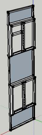
      The image may help to visualize it. The magenta rectangle is generated by the draw_geometry method of my tool, which also draws the face normal along what will become the @long_axis of the about-to-be-created component.

      Shows calculated face.normal visibly NOT normal to the top face of the component

      But as you can see in the drawing, instead of being normal to the face, the @long_axis is parallel to the green axis. (By the way, the 3x2 cursor text is the nominal size in inches of the cross section of the component about to be drawn, in case you were wondering.)

      The code which finds the face normal is derived from the sample ruby CLineTool:

      
      @ip1.pick view, x, y
      if( @ip1.valid? )
      ... other code...
      ## Detect if pick point is on a face, and if so, orient long axis normal to it
      #   unless axis is locked
      if @ip.face 
         f = @ip.face
         puts  "Face picked; normal is \n"
         puts f.normal.inspect
         if @@axis_lock == NO_LOCK # axis not locked
           @long_axis = f.normal
           puts "@long_axis = " + @long_axis.inspect


      This outputs in the Ruby console :

      
      Face picked; normal is 
      Vector3d(0, 1, 0)
      @long_axis = Vector3d(0, 1, 0)


      The code which draws the feedback geometry is:

      
      # Display long axis as visual feedback
        view.line_width = 2; view.line_stipple = ""
        view.set_color_from_line(pt1 - @long_axis, pt1 + @long_axis)
        view.draw_line(@first_pick.position, @first_pick.position + @long_axis) 
        ...
        view.drawing_color = "magenta" 
        view.draw_polyline(@profile_points)


      I find that if I open the component for editing, and copy and paste its top face into the World coordinate system, the face.normal IS normal to this face, which is in the red-blue plane, not at the angle it appears as the top surface of the component.

      I'm sure this is because I've originally drawn the far end face of the visible component in the r-g plane (as @profile_points0, which got transformed into @profile_points in the feedback view.draw.polyline above), then did the same transforms on the component face -- rotated it about two different axes and translated it -- then push-pulled it along (its) long_axis to generate the component shown.

      Yet (as you can see from the blue highlighted bounding box) the previous component axes are in line with its faces.

      In case it helps, I also attach the complete tool draw_framing.rb file.

      Any clues as to how to fix this would be most welcome. Until I discovered this 'bug' in my code, I thought I was nearing v1.0 of my code!

      So how do I reset the axes of the original face and the component which it becomes, to get a component drawn whose faces AREN'T weirdly distorted internally so as to throw off the apparent face.normal?

      I found (before I recoded it this way) that if I first made a group, then a component instance, it didn't have this problem, but its component axes were along world axes, not tightly around the shape of a non-orthogonal component. That is easy to fix manually with a Change Axes command, but there isn't an API function to do the same, afaik.

      If anyone knows how to do that, I could revert to that method of creating the component instance.

      For example, would it help to explode the component in code, then re-group it and make component?

      Or can anyone suggest an alternative approach altogether?

      Thanks in advance for any advice I could follow, to work round this.


      Code that generates this odd component

      posted in Plugins
      J
      johnwmcc
    • RE: Request for help in developing a new Tool

      Thanks again, TIG.

      posted in Plugins
      J
      johnwmcc
    • RE: Request for help in developing a new Tool

      I'm making progress on this, but I've run into another question.

      At one point, I need to find the angle between a vector in the X-Y (red/green) plane and the X_AXIS.

      I calculate

      
      # Calculate a vector (vec3) which is the projection of a face.normal onto the red/green plane
         vec3 = Geom;;Vector3d.new [face.normal.x, face.normal.y, 0]
         rotate3 = X_AXIS.angle_between vec3 


      Perhaps naively, I had expected the value of rotate3 to change sign if the direction of vec3 is rotated past the X_AXIS from (say) [1,-1,0] (-45 degrees) through [1,0,0] (0 degrees) to [1,1,0] +45 degrees.

      But it doesn't. rotate 3 is always positive.

      Is this because in the general case, the angle between two arbitrary vectors doesn't have a 'sense of direction'?

      So do I have to distinguish cases where face.normal.y may be positive or negative?

      Doing that with an IF statement works.

      But is there a more elegant way of calculating this angle, WITH a sign attached?

      posted in Plugins
      J
      johnwmcc
    • RE: [Plugin] 3D Parametric Shapes - makes placeable components

      Glad you got it going again with little trouble.

      posted in Plugins
      J
      johnwmcc
    • 1 / 1