sketchucation logo sketchucation
    • Login
    1. Home
    2. johnwmcc
    3. Posts
    ⌛ Sale Ending | 30% Off Profile Builder 4 ends 30th September
    J
    Offline
    • Profile
    • Following 0
    • Followers 0
    • Topics 18
    • Posts 105
    • Groups 2

    Posts

    Recent Best Controversial
    • RE: [Plugin] SketchUcation Tools

      I've installed SketchUcation Tools 2.0, apparently successfully, in SU Make 2013.

      I try to use Plugins Manager, and immediately get the error message


      SketchUp

      NO Security Permission to Manage ANY Plugins Folder in the $LOAD_PATH.
      FULL Read/Write Permissions are needed to Manage Plugins within Plugins Folders...

      OK

      I tried to fix this by changing Advanced Sharing settings in the Plugins folder, setting permissions for Everyone to All, and restarting SU.

      Also tried system restart after setting these sharing permissions.

      Still get the same message.

      Any further suggestions?

      I'm running Windows 7 Pro 64 bit, fully patched up to date, and the latest version of SU Make 2013.

      John McC

      posted in Plugins
      J
      johnwmcc
    • RE: Scaffolding fittings

      I attach a single drawing containing all the fittings I have drawn, saved as SU v8.

      John McC


      Contains one example of each fitting, saved as v8

      posted in SketchUp Components
      J
      johnwmcc
    • RE: Scaffolding fittings

      In response to jpalm32

      If you find you need any fittings that are in the Zip file, but not in the assembly drawing that ely862me has so quickly uploaded, let me know. I can save them as v8, and re-zip the file, but it will take a day or two before I am free to do it.

      John McC

      posted in SketchUp Components
      J
      johnwmcc
    • Scaffolding fittings

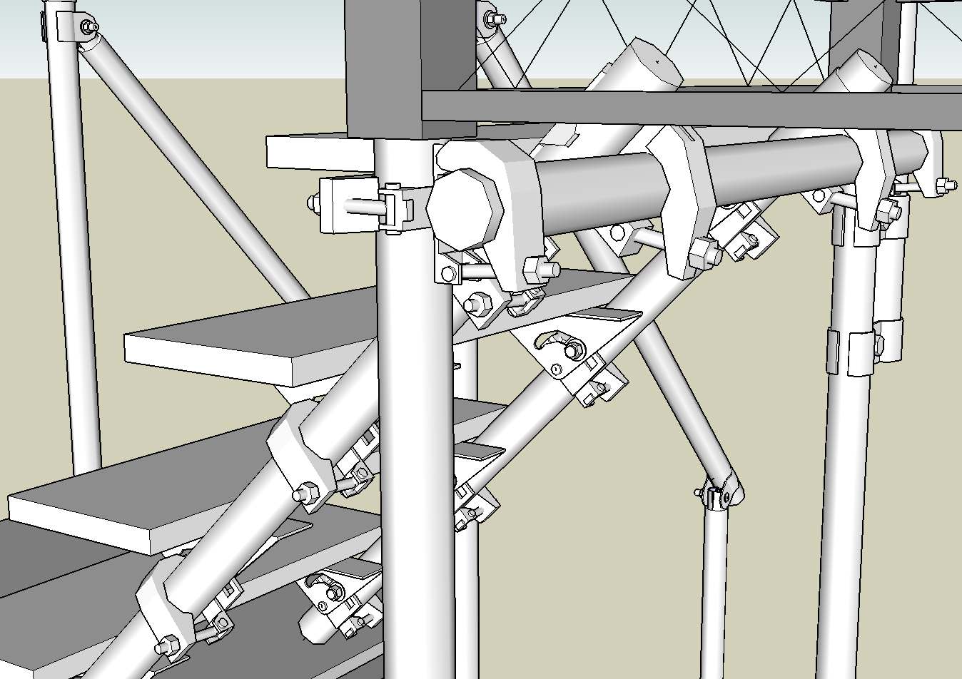
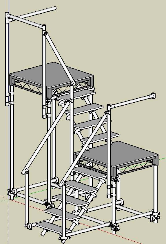
      Stair assemblyDetail view of part of the stair assembly, from the rear

      In the course of designing a stage set which makes extensive use of scaffolding, I have modelled a range of scaffolding fittings in Sketchup which may be of use to others.

      The play, Wuthering Heights, is to be performed at our amateur Abbey Theatre, St Albans, in November 2013 (see http://www.abbeytheatre.org.uk).

      To reduce the polycount in the main assembly models, the fittings are drawn somewhat simplified, and with only eight segments representing a circle. I use a slightly adapted version of TIG's plugin PipeAlongPath.rb to draw scaffold poles, also using eight segment circles for their cross section. In use, I place a line for the centreline of a pole, add a fitting or fittings, aligned on a centreline in the fitting, then create the pole as a 1.9 inch diameter cylinder. I assign a keyboard shortcut (I use Ctrl+Shift+A which can be 'typed' with one hand) to run the PipeAlongPath plugin on the selected line.

      Another line can be extended from the centreline in the other part of the fitting, and again converted to a cylinder using PipeAlongPath.

      I attach a zip file of Sketchup drawings of individual fittings, and an assembly drawing (Stair assy.skp) of part of the set, which illustrates the use of many of them. I also attach the modified PipeAlongPath plugin. It has been adapted to draw cylinders with an outside diameter of 1.9 inches by default, eight segments per circle. It makes a component of the resulting scaffold pole, and offers a prompt to name it after drawing it.

      I have found it useful to use the Xref Manager plugin to include the scaffold fittings, so that if any are modified, the assembly drawing can be easily updated.

      If a higher resolution/high polycount rendering were to be needed, the fittings could be redrawn with more segments per circle, but I haven't myself found a need for that.

      I hope these may be of some use to others.

      If anyone is interested, I may try (as a complete novice at it) to make a video of the process of drawing a scaffolding assembly, and add it to this post.

      John McC


      Zipped file containing Sketchup drawings of scaffolding fittings.


      Example of fittings in use


      Adapted PipeAlongPath plugin to draw scaffold poles on a line.

      posted in SketchUp Components sketchup
      J
      johnwmcc
    • [Plugin] 3D Parametric Shapes - makes placeable components

      Plugin and text revised 3 Dec 2014

      v2.5 (late Nov 2014) changes the drawn shapes from groups to components, and allows the user to place them at any pickable point, not just insert them at the world origin.

      v2.51 (1 Dec 2014) corrects internal version number labelling in jwm_shapes_loader.rb and jwm_shapes.rb files to match external version number

      v2.5.2 (1 Dec 2014) corrects error introduced in parametric.rb where a typo in the Module name stopped plugin from loading.

      v2.5.3
      Fixed name errors in modules that broke Torus, Dome and Sphere which relied on mesh_additions.rb.

      © John McClenahan 2014 and Trimble Navigation Ltd Sketchup Team 2014
      Purpose
      This plugin enables Sketchup users to draw and subsequently edit a range of common
      geometric shapes by specifying in a dialogue box their size and (where relevant) the number of segments to use when drawing shapes based on circles, polygons, or helix.

      The plugin installs a 3D Shapes sub-menu in the standard Sketchup Draw menu, with a selection of shapes chosen from a sub-sub-menu:

      • Box

      • Cylinder

      • Cone

      • Torus

      • Tube

      • Prism

      • Pyramid

      • Dome

      • Sphere

      • Helix

      • Helical Ramp

      • Helical Ramp with Sides

      Edit the parameters to the desired size and (where relevant) number of segments or sides to use, and click [OK]. The shape is then drawn located at the axis origin [0,0,0] as a Group.

      The drawn shape can be undone in one operation using Ctrl+Z or Alt+Backspace keyboard
      shortcut, or using the Edit/Undo menu. Once undone, it can be re-done by using the menu
      Edit/Redo… Shapes, or Ctrl+Y immediately, before issuing any other command.

      When any previously drawn 3D Shape is selected, a right-click Context menu (Edit…Shapes)
      allows the user to change any of its defining parameters using a pop-up dialogue.

      The plugin uses two other Ruby scripts – parametric.rb and mesh_additions.rb – which are
      included in the .rbz plugin file and automatically installed along with the shapes.rb file.

      It has only been tested by me on Windows 7 Pro and Sketchup 8, 2013, 2014 and 2015 but will probably work on earlier versions of Sketchup, on Windows XP or later. I have no way of testing it on a Mac.

      Language is English only.

      What's new?
      My additions extend the original Trimble Sketchup Team plugin to provide:
      • FOUR additional shapes – Sphere, Helix, Helical Ramp, and Helical Ramp with Sides
      • User selection of the number of segments to use when drawing shapes based on a circle,
      not just a fixed default (usually 24 in the original plugin)
      • Drawing a Pyramid with any number of sides in its base polygon, not just a square base
      • Default sizes remembered from the previous use of that shape in the same Sketchup session
      • Initial default sizes on first use of a shape are selected according to the model units and unit format, usually one unit for length, height, width, depth or radius (using feet, inches or metres) or 10 units for millimetre and centimetre units (10 mm or 10 cm)
      • The initial default number of segments to draw is set at 16 for most shapes, and 4 per 90 degrees for Dome or Sphere. It can be changed by the user (and will be remembered for
      the duration of the Sketchup session)

      Helical shapes will be drawn upwards from the origin (by default, with end height higher than start height), or downwards by setting the start height higher than the end height.

      Helical shapes can be made left handed by setting No. of rotations to a negative value.

      Helical shapes can be drawn starting at any specified start anglefrom the x-axis.

      The helical ramp further adds to the helix, and draws an (optionally tapering) helical ramp surface, with ramp starting width, ending width, start and end height parameters.

      [To make a permanent change to the initial default number of segments, edit the shapes.rb
      file default_parameters method for each shape Class, and change the line @@segments = 16 to your desired default.]

      The code to draw the Helix is adapted from DrawHelix13.rb by Peter Brown (2004) and DrawHelix14.rb by Jim Foltz (ca 2010), which was an update of Peter Brown's plugin.

      Installation
      In Sketchup v8 M2 or later (including Sketchup 2013, 2014 and 2015) both free and pro versions the plugin is installed in the normal way via the Window/Preferences/Extensions menu [Install Extension] – see http://help.sketchup.com/en/article/38583. I have also submitted the plugin to Extensions Warehouse. When accepted there, it should be possible to install it directly from the Window/Extensions Warehouse menu in SU 2013 or 2014 (now compatible with SU2014).

      It can then be activated or de-activated from the Window/Preferences/Extensions menu by
      ticking or un-ticking the box beside the plugin name. Shapes Tool.

      If you are using an older version of Sketchup, change the file extension of the plugin from .rbz to .zip, and extract the contents to the Sketchup Plugins folder (see the help article above for the default plugin folder location on Windows or Mac.)

      Download the latest version from the Plugin Store at
      http://sketchucation.com/pluginstore?pln=jwm_shapes
      posted in Plugins
      J
      johnwmcc
    • RE: [Plugin] 3d Shapes Tool (was: Pyramid Tool)

      I've just tried this in Sketchup Make 2013, as this no longer has the 3D shapes built in to the free version.

      It crashes Sketchup completely every time ("The Sketchup Application has stopped working"), on the third click to set height(for cone or pyramid) even after system restart, and using the plugin in a completely new drawing.

      There's no error message in the Ruby console, just the crash. Entirely repeatable, unfortunately.

      Is there an update available that would fix this?

      I can't find any other equivalent plugin: if anyone knows of another, I'd be grateful for a pointer to it.

      John McClenahan

      PS. Have just found the Shapes plugin by the Sketchup team, in the Extension Warehouse. That will do very well. In earlier versions of SU I thought it got installed by default, but it wasn't in SU Make 2013.

      posted in Plugins
      J
      johnwmcc
    • RE: [Plugin] Arcs Circles +

      This is a very useful plugin. But I find when I use (for example) Arc: Center, 1 Point, Angle that once you have clicked on Center and Start point, the VCB won't accept the angle. The data entry box is still white, but goes yellow after you press Enter, doesn't accept the typed value, and won't accept further input.

      I only worked out by experiment that you haveto enter the Angle beforeyou click on Start point, which I find counterintuitive.

      Could it EITHER be relabelled Arc: Center, Angle, Start Point, OR (better) continue to accept VCB input after the click for start point, ideally until the next operation is started, so you can (if possible) amend the value to get the result you need?

      It isn't consistent with the way the Arc: Center, 1 Point, Length works, which DOES accept the length after you click on the start point.

      Arc: 2 Points, Angle and Arc: 2 Points, Radius have the same problem - you have to enter the VCB value for Angle or Radius beforeclicking for the second point. Again, I find this counterintuitive, and initially thought it was a bug, until I found the way round it by typing the value before the second click.

      I have downloaded the later version of arcscircles.zip attached to your post of 22 August 2013, and checked that these still seem to be problems even in that version.

      I'm using SU Make update M2, on Windows 7 Pro 64 bit, in case that makes any difference.

      Thanks for continuing to develop these very useful extensions to native SU.

      John McClenahan

      PS. Just to be sure I have the latest version, I later downloaded the v2.0.2 RBZ file from the top of this thread. Same problem. The VCB accepts and remembers the value typed for the first use of the command, but ignores it for what is drawn. However, it DOES remember and use it for the SECOND use of the command, but still won't use a new value if it is input after the second click.

      Still seems counterintuitive to me.

      posted in Plugins
      J
      johnwmcc
    • RE: Draw a new component with axes at original pick point?

      I'll try the pick_helper, then. Thanks again.

      posted in Developers' Forum
      J
      johnwmcc
    • RE: Draw a new component with axes at original pick point?

      I don't think I have a handle for the component_instance that I click on - just the @ip1 pick point - so I'm not sure how I'd use your suggestion, TIG.

      But I think Martin Rinehart's Edges to Rubies might have the clue - the translate elements of the @tf.to_a array elements 12, 13, and 14 will contain the coordinates of the picked-on component's origin, I think. (Must look it up to be certain.) Will try this later today, and see if it works.

      John McC

      posted in Developers' Forum
      J
      johnwmcc
    • RE: Draw a new component with axes at original pick point?

      Well, I'm ALMOST there, following the advice so generously and quickly given.

      My first two points are the initial picked point @ip1, and the current mouse position @ip. I pick on a corner of an existing component, NOT at its origin, drag the mouse to place the cross-section in the correct orientation, then click again.

      In the method onLButtonDown on the first click I set a transform @tf = @ip1.transformation.

      I pass the position of these points to the method 'draw_geometry(pt1, pt2, view)' where pt1 = @ip1.position and pt2 = @ip.position.

      I copy the points defining the cross-section into an array @pts0[] with one corner at the origin. I then transform these points to @pts[] using

      @pts0.each_index {|i| @pts[i] = @pts0[i].transform(@tf)}

      I can then draw the cross-section in the method 'draw_geometry(pt1, pt2, view)' in the right orientation using view.draw_polyline(@pts), and also draw the cross-section as a component @comp (initially just a face) at the origin in 'create_geometry(pt1, pt2, view)', then move and rotate it back to (almost) where I want it using

      @comp.move!(@tf)

      But in both cases, the cross-section is drawn NOT at the location @ip1 (which is where I expected it to go), but at the origin of the existing component on whose corner I clicked.

      If I click somewhere in the model not on a component, the cross-section is drawn correctly oriented at the World origin, not at @ip1.position.

      I thought that the @ip1.transformation would transform a point [0,0,0] to the location of the pick point @ip1, NOT to the origin of the component it is located in (or World origin if the pick point is not located in existing geometry). I seem to have misunderstood this.

      How can I retrieve the coordinates of this component origin, so as to define a vector from there to @ip1.position, and locate the cross-section correctly?

      Thanks again in advance if you can help further.

      John McC

      posted in Developers' Forum
      J
      johnwmcc
    • Draw a new component with axes at original pick point?

      I'm progressing slowly with my planned Ruby to help draw timber frames, based on Jim Foltz's CLineTool, and with help from TIG in response to a couple of previous posts.

      So far, I can get it to draw a 'box' shaped component correctly aligned with any World axis, with a bounding box properly aligned around the component.

      But I can't see how (in Ruby) either to draw the component with its axes at the first pick point, or to re-locate the component's axes from the World origin to the original pick point after it's been drawn. Whatever I try, I seem to draw the component with its origin at the World origin.

      The component is drawn by adding a face from an array of Points3d that define the cross-section of the timber relative to the pick point in the desired orientation, drawing them in World location by 'adding' the pick point position, then switching to the built-in PushPull tool to pull the face out to the desired length.

      I've searched the forum, but can't find any examples of code that quite address this issue, except one old one which basically says 'you can't use Ruby to relocate a component's axes.'

      Even if that is still true, is it possible to draw the first instance in Ruby with the component axes at the pick point? If so, how?

      Alternatively, do I have to draw the face (preferably without displaying it) at the origin, then move it to the pick point in preparation for the user to make it into a box using the PushPull tool?

      I think I could probably get that to work but it seems a bit inelegant.

      Thanks if anyone can advise me.

      John McC

      posted in Developers' Forum
      J
      johnwmcc
    • RE: Using View.draw_polyline in rotated component

      Thanks very much, TIG, for such a quick and helpful response.

      It's helped a lot to clean up the code, and it now works for two cases: when @ip1 is clicked at the global origin, or on a component origin.

      But is still isn't right if you click on a point or intersection or another component, inside the original component. The long axis line moves to the clicked location and correct orientation in all cases, but the rectangular polyline defined by the point array in cross_sect is still mislocated, though correctly oriented, though it's now closer to the clicked point, instead of a long distance away.

      I suspect it's a problem with the way I've defined the points in the cross_sect[][] array, and will try a few more test cases to see if I can get to the bottom of it. I'll also try defining the cross section by a series of lines defined as vectors, instead of an array of points, to see if I can understand better just what's happening.

      Can one declare an array of 3d Points as follows?

      cross_sect = [Geom::Point3d.new]

      I've tried both with this definition (which doesn't error, but may not be meaningful), and just declared as an Array, but get the same not-quite-right results.

      I'd post an image here if I could work out how, or perhaps upload a copy of the Ruby if that would be useful, but not just yet until I've worked on it a bit more myself.

      Thanks again for your support to a Ruby programming newbie, and for writing so many useful plugins yourself!

      John

      posted in Plugins
      J
      johnwmcc
    • Using View.draw_polyline in rotated component

      I'm trying to develop a plugin to help in drawing simple timber frames in standard UK timber sizes. I'm starting by extending the CLineToolplugin written by Jim Folger

      I've got as far as being able to draw a polyline on a component 'box' to show where the cross-section of the timber will be placed, provided that the component is orthogonalto the world axes.

      I can also draw a line to show the long axis of the wood, using the View.draw_line method between the two points (pt1 + @lAxis) and (pt1 - @lAxis). (@lAxis has only one non-zero coordinate).

      I have found the InputPoint.transform method to return the transform of the component at the original pick point, in the onLButtonDown method.

      @ip1.pick view, x, y
        if( @ip1.valid? )
        # call the transformation method to get the component/group instance Transform vector#
        @tf = @ip1.transformation


      I can then rotate the long axis line to match by applying the transform to the line defined by the draw_geometry method (which is called from the draw method in my new Class replacing the originals in CLineTool).

      But I'm stumped in trying to apply the transform to the rectangular polyline.

      This works when the component axes are parallel to the world axes:
      I set

      #Direction of long axis of wood (normal to plane of cross-section)
      @lAxis = Geom;;Vector3d.new 
      ...
      view.drawing_color = "magenta" ; view.line_width = 2; view.line_stipple = ""
      @lAxis[n] = d*2.0 # Set long axis direction normal to @plane, and twice the depth of the wood
      @lAxis.transform! @tf
      view.draw_line(pt1 - @lAxis, pt1 + @lAxis) # to show direction of long axis of wood
      pts = []
      pts = [pt1, pt1 + cross_sect[n][0], pt1 + cross_sect[n][1], 
      pt1 + cross_sect[n][2], pt1]
      view.draw_polyline(pts)


      (cross_sect[n][0]..[2] each contain a 3-element array with the coords of the three corner points of the wood which aren't at the pick point. The value of n is the direction of the normal to the cross section - 0 = R direction, 1 = G direction, 2 = B direction.)

      The onMouseMove event orients the cross section polyline in the view, before the second pick, according to the relation between the first pick point and the current mouse position, to change the plane of the rectangle in the draw method of the tool, and also the direction of the longer cross section.

      But I simply CANNOT work out how to apply the same transform to to the polyline points (or the whole polyline) so as to rotate the rectangle around the first pick point to match the component's orientation. At best, I can get it in the right orientation, but a long way from the pick point - as if it has rotated round the global origin rather than the pick point.

      This is the best I've achieved:

      
      pts = [(pt1.transform @tf), ((pt1 + cross_sect[n][0]).transform @tf), 
      ((pt1 + cross_sect[n][1]).transform @tf), ((pt1 + cross_sect[n][2]).transform @tf), (pt1.transform @tf)]
      view.draw_polyline(pts)


      I thought that since the @lAxis.transform seemed to work to generate a vector relative to the first pick point, the polyline points would behave the same. But they don't seem to.

      Earlier attempts were plagued by syntax errors, and semantic nonsenses, but I finally got at least the syntax of this right so that it drew SOMETHING - it now changes orientation correctly as the mouse moves, and pivots round the same point, but that point isn't in the right place.

      Is there a simpler way to achieve the reorientation and relocation of the drawn points to match the rotated component axes AND get them in the right place?

      Perhaps I need somehow to 'subtract' the translation element of the pick point from the origin, but I can't work out how to. And since I'm relocating each of the polyline points individually, in a similar way to the @lAxis points, I thought the transform would correctly relocate the polyline.

      @lAxis is a Vector3d (and didn't work until I made it one - before that, I could draw a line from pt1 to (pt1 + @lAxis), but not to (pt1 - @lAxis)).

      The elements of cross_sect are just arrays, not Vector3d objects. Does that matter?

      Or should I try to do it all with the draw_linecommand rather than draw_polyline?

      Any help, or a pointer to code that does the same thing, would be most welcome.

      Thanks if anyone can help. In the meantime, I'll re-read Martin Rinehart's later chapters in Edges to Rubies on transformations, to see if I can work out where my logic is going wrong.

      posted in Plugins
      J
      johnwmcc
    • RE: Using View.draw_text method - a bug?

      Many thanks. For some non-obvious reason, I didn't even SEE the screen_coords method of the View object. I was looking for an equivalent method or property of the point itself.

      Gratefully....

      John MCC

      posted in Plugins
      J
      johnwmcc
    • Using View.draw_text method - a bug?

      I'm running SketchUp v8.0.11752 on Windows Pro 64bit, and trying to get my head round developing a new Tool to draw shapes using a variant of Jim Folger's CLineTool.

      At the moment, I'm trying to understand how to use the View.draw_text method when providing feedback to the user.

      The documentation says that the two arguments are a Point3D object, and a text string to display.

      When I test it using the [0,0,0] representation of a Point3D, the text is shown during the tool's operation at the SCREEN coordinates of [0,0] - right up at the top left of the SketchUp drawing area, NOT at the axis ORIGIN.

      Similarly, if I give it the (3D) input point at the cursor, the text moves with the cursor as expected, but around the top left screen position, going partially out of view some of the time. It seems to be taking only the r and g values of the 3D input point and displaying the text a proportionate amount of right and down displacement from the top left of the drawing viewport.

      Is this a bug? Or am I just not understanding how to feed the cursor location properly to view.draw_text? I'm using the same routine to draw test CLines, and they are starting in the right place both on screen and in the model.

      I've searched this forum, and Googled for view.draw_text, but can't find anything relevant other than the API documentation. I'm still very new to Ruby programming, and so far have only manage minor adaptations of other's code. At least I THINK I now understand how (almost) all of CLineTool works.

      But I don't find it easy to work out from the API docs how to use things for anything more complex than their (usually very simple) examples with static values, if I can't find another plugin that uses it. (And I do have a science and maths background to PhD level).

      Any help would be appreciated.

      John McC

      posted in Plugins
      J
      johnwmcc
    • RE: Getting error in Layer Manager v2

      I posted earlier about a problem in getting Layer Manager to do anything after apparently successful installation.

      I had to reinstall Sketchup for other reasons, and I find that Layer Manager now works. So perhaps something had gone missing, either in the built-in files that Layer Manager uses, or in the Windows Registry.

      Anyway, problem solved.

      John McC

      posted in Developers' Forum
      J
      johnwmcc
    • Getting error in Layer Manager v2

      I have just downloaded, unzipped, and installed in the Plugins folder Didier Bur's Layer Manager v2, including the Layer Manager folder and its contents, as instructed in the PDF.

      It loads without error and displays the toolbar, but none of the buttons appear to do anything when clicked.

      In the Ruby Console, when I click (for example) the first button 'Set layer of selection current', I get this error message:

      Error: #<NameError: undefined local variable or method lm_set_current' for main:Object> D:/Program Files/Google/Google SketchUp 6/Plugins/layer_manager_extension_v6.rb:33 D:/Program Files/Google/Google SketchUp 6/Plugins/layer_manager_extension_v6.rb:33:in call'

      I have tried it both with nothing selected in the drawing, and with an object selected - same error message, and nothing happens. And similar messages appear for a few other buttons that I tried - 'undefined local variable or method ...' with different names corresponding to the different buttons.

      A Google search for the error message turns up nothing, either in this forum, or the wider Internet.

      The only two things I can think of that are not entirely standard in my installation of Sketchup, are that it is installed on the 😧 drive, not the 😄 drive; and that I had an educational Pro licence, which I have not renewed - but I thought that merely reverted the program to behave like the free version.

      I have tried to look in the \Plugins\layer_manager_v6.rb script to see if that would point me in the right direction, but is is encrypted.

      Any suggestions, please, for what might be preventing this from working? I have a good number of other Ruby scripts, which all seem to work fine. And I used the earlier version of Layer Manager and found it very useful, so would really like to get this to work.

      Thanks if anyone can point me in the right direction to fix this. I can do simple Ruby scripting, but not enough to diagnose this error.

      John McC

      posted in Developers' Forum
      J
      johnwmcc
    • RE: How do I select the built-in Rotate Tool in a script?

      Well, progress of a useful kind. I've worked out from the sketchy API for observers how to define an observer to monitor the 'onComponentInstanceAdded' event, and got it to pop up a messagebox when the user has picked the insertion point after the script generates and inserts the component.

      Now to add the code to select the Rotate tool, instead of the messagebox (which is where I came in!)

      posted in Developers' Forum
      J
      johnwmcc
    • RE: How do I select the built-in Rotate Tool in a script?

      I get the general idea. Can you point me to a script that uses an observer in this way, or something like it? As always, the hardest part for me is seeing how the various classes and methods work in practice, and how to string them in a usable sequence.

      In principle, I assume I set up an observer to start watching before the place_component, wait till it 'sees' a pick to place the component, then somehow 'lets go' after the pick, to allow the rotate tool to be selected. But the details of how to do that are still not easy for me to work out just from the class and method definitions. Many of them have either no examples, or extremely basic ones that do no more than illustrate simple syntax, with little idea of the semantics or meaning of the code, or how to build up to more complex uses.

      Anyway, I'll have a go.

      JohnMcC

      posted in Developers' Forum
      J
      johnwmcc
    • RE: How do I select the built-in Rotate Tool in a script?

      That's a very useful reference, thanks again. Now I know how to select ANY programmable action. But it doesn't seem to include the action I now think I have to perform first, before rotating.

      I've experimented with the command to select the Rotate tool, and find a further problem in what I'm trying to do. If I just add the script line to choose the RotateTool at this point, it interrupts the place_component command which was the previous line in the script, where the user was left to pick the insertion point. So the inserted component disappears, not inserted, while the Move tool that is waiting for a click to place the component is replaced by the Rotate tool in the user interface, with nothing now selected to place OR rotate.

      Is there a way to tell Ruby to wait till the user has completed the previous command (to pick the insert point), before then selecting the Rotate tool to rotate the inserted component? I can't see where to look for how to do this, and if you can point me in the right direction, I'd be very grateful. I've searched both in Google in general, and in this forum, for different permutations of the words 'sketchup ruby wait user input' without success so far.

      The only hint I've found, which looks extremely complex, is to define a new tool, based on, for example, the supplied scripts Linetool.rb or the TrackMouseTool in utilities.rb which can do some or all of the picking within the script. But it seems a lot of work, when the right one-line command might do what I need here, if only I could see what it might be!

      JohnMcC

      posted in Developers' Forum
      J
      johnwmcc
    • 1 / 1