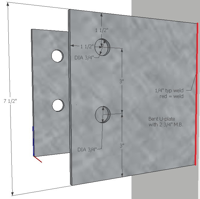
I have a component with a hole in it in my picture. How can I list the diameter of that hole in the main drawing? I can only select the hole when I'm editing the component.
Posts
-
Diameter of a hole in a component listed in full pic?
-
RE: Dimension what can be measured at least
@gaieus said:
Well, I don't know but I can dimension a radius starting from the centerpoint to the perimeter of the circle of a punched hole:
@banaticus said:
If you have a sheet of steel with some holes punched in it and you want to show the dimension from the center of a hole to the edge of the steel...
Not to the edge of the hole, to the edge of the steel plate. For instance, dimensioning from the middle of these holes to the edges of the U-bracket, because when you're laying something out you measure from the edge to the center of the hole that you're about to drill. I usually use diameter instead of radius because drill bits are listed by diameter.

Yes, that top left corner is busy (and the 1 1/2 should possibly be to the right in line with the 3" measurements), but that's the way they wanted it and of course I want whatever they want.
 As far as dimensioning goes, I really wish that I could choose both the rotation of the diameter line and the placement of the text, but the placement of the text automatically forces a particular orientation of the diameter arrows.
 -
RE: Dimension what can be measured at least
If you have a sheet of steel with some holes punched in it and you want to show the dimension from the center of a hole to the edge of the steel, you can't. If you start from the edge, it just gives the dimension of the edge itself. If you start from the center of the hole then it won't snap to the edge of the steel. What you have to do is to draw a line from the center of the hole to the edge, then draw another line off at an angle, then delete the first line (which is in two pieces since it crosses another line where it crosses the outside radius of the hole), the snap the dimenion from the center of the hole to the base of the angled line (which is on the edge of the piece), then you can go and delete the angled line.
So frustrating and time consuming.
Also, the way you can move a dimension or text tag around but you can't choose what side it's on. For instance, if you have a long tag, you might want to make the line coming back under the tag like a sideways V with one leg as the tag and the other leg going to the point, but you can't. If you pull the arrow away, then the tag goes even farther away like a big tilde ~.
-
RE: Lock toolbars
@remus said:
...except office 2007

Well, Microsoft has the official stance that things can't be removed from the Ribbon... but what they don't advertise is that you can hide things on the Ribbon and otherwise move stuff around (and add new things): http://msdn.microsoft.com/en-us/library/aa338202%28office.12%29.aspx#OfficeCustomizingRibbonUIforDevelopers_Customizing
I would really really like to see the ability to do something like that, some sort of coding or CSS or XML or something that would allow us to upload a customized UI from a file. There are a few things that I like to use regularly that I just can't do with keyboard shortcuts, like the Dimension tool for callouts. I've set it to the "D" key, but then there's that layer-pane thing that sizes itself to cover the model and which "hides" (removes) everything on one side of it -- I love sliding that thing back and forth to quickly remove a wall.
-
RE: What's the difference between faces
Is it possible to build a box that has all of its outside faces on the inside? Perhaps that's why Hammer is rejecting the things I've been building in SketchUp. Is it possible to make the faces more obvious? Like, some setting that has one side blue and one side red or something and a way to know clearly which side is which?
-
What's the difference between faces
What's the difference between one side of an object and another? What's this reverse faces thing? They both seem to take a texture just the same.