I don't think this was done is SketchUp, but there's no reason it could not have been.
Posts made by August
-
Fly Like a Bird
-
RE: An exercise: DRAWING A PARISIAN FENCE
Please forgive me reviving an old thread but this entire thread is definitely one of my all time SketchUcation favorites. The depth of tutorial information in this thread is just awesome.
AND, there is new and hopefully relevant information to add. The GIF that by Cosycat that was posted by simon le bon on Sun Jul 25, 2010 has now officially gone viral.
I have seen it as the Profile image on Facebook by someone who had never heard of SketchUp. It is also regularly used by "vsauce" as a background in many of his videos, as seen here starting at 0:25.
Just FYI.
August
-
RE: Scenes and Physics Simultaneously?
@ace baker said:
... if someone can get my animation exported to a quicktime movie. The physics simulation and camera movements all work fine. I capture the animation fine. For some reason when I export the animation, it's missing the physics. ...
Ace, did you ever solve this?
-
RE: Access to Dimension Line text?
@dan rathbun said:
For the record, I never said each entity, I said ...
@dan rathbun said:certain types of entities, that have the specific named dictionary
Thanks for keeping that key concept on the table after I skipped over it.
-
RE: Access to Dimension Line text?
FYI, for anyone following this, now or later, here is the link to TIG's plugin:
[Plugin] Add Height from Datum v1.3 -
RE: Access to Dimension Line text?
@thomthom said:
Doing that automatically for each entity would probably make SketchUp crawl to sludge when loading large models.
That is what I was alluding to when I wrote:
@august said:
It would probably require building a Lookup table, and rather than do that when you open the file, and thus do it for every file, it would be better to it when you manually access a menu item that updates the Text Entity Tags.
My thought is that you should manually trigger the updating and table-building process, maybe with a progress bar, so that at least it only happens when you are prepared for it happening, and most especially it does not happen on every file, whether the tool is used or not, just because the Plugin happens to be loaded.
It might be a timesaver to have the option of scanning the whole file, or just the selected part of the file.
-
RE: Access to Dimension Line text?
I had forgotten that Entity or Object IDs are not persistent. Neither are Arrays.
Right now TIG's Add Height from Datum seems to handle the basic idea for contour lines. But it is self-contained, referencing the hight of the Text Element point itself. To display data in a Text Element about another object means linking the entities, which is, of course, where the Unique Identifiers come in.
Thanks, Dan, for a great idea on where to get unique identifiers to add to an object's attributes.
It would probably require building a Lookup table, and rather than do that when you open the file, and thus do it for every file, it would be better to it when you manually access a menu item that updates the Text Entity Tags.
I'm going to let this one percolate for a while. If most of the substructure had to be created to do the contour lines and extending it was the simpler part, that's one thing. But since the contour lines is solved and extending it is not really extending anything, it's creating a whole new methodology, that's another thing.
Thanks again to all.
August
-
RE: Access to Dimension Line text?
Thanks TIG.
Clear, helpful ... and frustrating.
Oh well. It seemed to be a good idea at the time.
Hmm. Maybe I don't need the Dimension Line at all, at least for the Contour Line case. (The tiny dimension case, I am stuck for ideas.)
Maybe I could add an attribute to a Text Entity that would save the Object ID of the Contour Line. Save all of those special Text Entities in a List.
Loop through the list and for each Text Entity, get the attribute and the Object ID, determine the elevation of the ID-ed Object, format that, insert it as the Text.text.
I had thought that I could use parallel lists of Text Entities and Contour Lines, but I think it will be cleaner to add an Attribute. That will allow you to select a single Text Entity and update it.
Hmmm. If I have an array of Text Entities that I'm holding onto and the user deletes one of them, what happens to the array? I presume it does not automatically shorten, it now has an element that points to a Null Entity, right?
While a user will have to use my "Magic Contour Line Add Tag" function to add a linked Text Entity, they are not so limited in deleting. I cannot be sure that they would always use my "Magic Contour Line Delete Tag" function for deleting.
So it would be best to just let them Delete normally and I figure out what they have done when I stumble upon a Null Entity in the list and just clean it up myself on the spot.
This is beginning to sound more do-able than I had feared.
For the contour line, I think I would need to look at the min Elevation and the max Elevation and if they are different, display both, if they are the same, display a single value.
I'm starting to think it could be made generic.
Right Click on any object and select "Add TAG". That would pop up a menu of attributes to display, X, Y, Z, MIN [X,Y,Z], MAX [X,Y,Z], [X,Y,Z]-extent, ... ObjectID, etc. Optional identifier (e.g., "Min-Y =").
Select the item and a Text Entity is created that displays that value.
That could be useful.
If this idea inspires anyone, please feel free to run with it. Just let me know.
It will be a week or two before I can begin banging on this. I have time for brainstorming and testing, but coding will be slow because of how many of these pieces I've never done before.
Thanks again for pointers.
August
-
RE: Access to Dimension Line text?
Thanks.
When you get a Dimension Line as a drawing element, perhaps by the user selecting it, can you get its properties such as length?
Perhaps it would still be possible to do what I am thinking of, not by accessing the text of the dimension line but just by accessing its length, thus taking advantage of the fact that it stays attached to the moved contour line.
Also, I suppose I should have asked this in the first place, are Callout Text object accessible to where the displayed text could be programmatically changed?
Thanks again,
August -
Access to Dimension Line text?
Is it still true that there is no API access to Dimension lines?
I found a note in this forum from 2007 that said I was SOL, but is that still true?
If there is access now, is there access to the text of a DLine?
What I'm thinking of, and do not know if it is possible, is to link a text Callout to a Dimension Line (somehow, maybe just adding an attribute to each with the object ID of the other) and then updating the text in the Callout whenever the value of the Dimension Line changes.
(Maybe you would have to run an update routine periodically or manually to get the values in sync, but that is a separate issue.)
I have two uses for this. One is to add a callout when the space pointed to is too small for the dimension to be readable. The measuring Dimension Line could be hidden and the callout would display the value.
The other is to add elevation text to contour lines. Dimension Lines could be added to each contour line, from the line to a zero-elevation surface, and then callouts with a zero-length leader would be added to the contour lines so the elevation of each contour line would be displayed superimposed on it.
But these ideas are moot if there is no access to the text value of a dimension line.
Any ideas?
And feel free to pick this up and run with it. I'm more interested in having the tool than creating it.
Thanks,
August -
RE: Snap Alignment
@ronb said:
I'm also interested in such a snap-point module. ...
Hi Ron,
May I invite you to share your application idea?
My experience has been that developers are often motivated by the idea that they are solving real problems for real people. The more you can help them see their work as connected to the real world, the more motivated they are.
That is why I was so verbose above in my ideas for how such a plugin would be used. Legos and Blox are just ideas to stretch the range of applications, my real motivation is for model railroad track.
The first 3D application that I spent any real time with was one aimed at model railroaders, but it was such a general purpose 3D design tool that I got hooked on it for that. I had done some model railroad building in high school and that gave me the shared vocabulary with the rest of the user base, but I was not, and still am not, a modeler of that kind.
That entire field could benefit hugely from SketchUp, but the inability of SU to deal effectively with track design issues is a real obstacle. Snap Alignment would solve that.
What's your application, if I may ask?
I hope this helps,
August -
RE: Re: Some Funny Pics.
@d12dozr said:
[YouTube - Realistic 3D projection on a building]
Fascinating imagery. You get a few clues to how it works along the way, but at the very end, when there's the sponsor's monitor mid-scene and it goes very bright, you can see how the bright rectangle illuminates the underlying building.
Mostly what they do "to" the building is dark so you can't see the real building because there is no light.
Clearly the entire thing was designed to project in just that position on just that building, sometimes having parts of the image aligned with the windows on the underlying building. Occaisionally there are bits where "it just can't be helped" and you see the underlying technique.
Very cool.
-
RE: Re: Some Funny Pics.
When I saw this, I immediately thought of this thread.
-
RE: [Plugin] Shape Bender Beta
Hi Gilligan,
My apologies, I just discovered I've been leaving out the second G in your name.
August
-
RE: [Plugin] Shape Bender Beta
Hi Gillian,
I suspect that you don't have a complete mental model of what and how Shape Bender is doing what it does, and that is the source of your confusion both in conceptualizing how to apply it to your task and your problems with using it.
I downloaded your SKP file and attempted what you had apparently been attempting.
(For clarity I try to use consistent terminology: Source Object, Guide Line, Target Curve, and Result Group. That way, if they are shortened to Object, Line, Curve, and Group, it can still be unambiguous.)
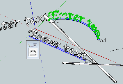
I tried to bend the undistorted "Enter Text" as the Source Object using the line immediately under it as the Guide Line and the curved line nearest to it as the Target Curve. Here is the result, before pressing Return to accept it:
[attachment=0:3212bbj0]<!-- ia0 -->Trying to duplicate bentText2<!-- ia0 -->[/attachment:3212bbj0]
(I have the Shape Bender Toolbar floating in the middle of the drawing area.)As you might infer from the image, I had no problems. I opened your file, I clicked the Source Object, I clicked the tool button in the toolbar, I clicked the Guide Line, I clicked the Target Curve, I captured the image. Note that Start and End are still indicated for both the Guide Line and the Target Curve and the proposed Result Group is still green because I have not pressed Return yet.
Here are a couple of pieces I wrote a while back that might help:
@august said:
It works as if the Shape Bender picks up the object and the guide line at the same time and then bends, stretches, or shrinks the guide line to fit the target curve, bending, stretching, or shrinking the object along with whatever it does to get the guide line to fit onto the target curve.
Depending on the shape of the target curve, the size of the bending object, and the distance between the guide line and the bending object, some parts of the object may be compressed while other parts may be stretched. But regardless of stretching or compressing of the object, one segment of the bent guide line is created for each segment of the target curve.
Feb 26, 2010, Page 25 of this thread.
@unknownuser said:
Shape Bender slices up the Original Object with vertical slices, according to how many segments there are in the Target Curve. One of the keys to predicting how it is going to work is that it will keep those slice faces vertical. It will rotate them in the Red-Green plane, but the slices will stay vertical.
The result is that for vertical curves Shape Bender projects the shape onto the curve vertically, for horizontal curves, it fans out and compresses, which is typically what you expect.
Apr 27, 2010, Page 30 of this thread.The above description of how Shape Bender works provides the answer to your question:
@gilliganu said:
... It does seem curious, to me, that if the shape bender can follow arbitrary lines in 3D, why the orientation of the model matters. ...
The orientation of the model is critically important because that determines how the Source Object gets sliced up so that it can be bent. Most problems with Shape Bender seem to come from people assuming how an object "ought" to bend that unconsciously includes internal stretching/shrinking that is does not match how Shape Bender slices up the Source Object. That is how the orientation of the model matters.
Unfortunately, right now the only "manual" for Shape Bender is this discussion thread, and right now that is 532 posts in 36 pages. A while back I offered to Chris that I would collect the best stuff from the thread and edit it into a manual, but I haven't gotten to it yet. I hope the above bits aid in clarifying things for you. If not, there's probably something from someone else in here somewhere (the Search This Topic tool at the top of the page may be of use).
On that topic, I was unable to duplicate your bending of the text, where part of the final "t" went off at an angle. It looks a lot like the trouble you were having with the cylinder earlier. If you can duplicate the problem, I would like to know what you did, because if I ever put that SB manual together, it would be useful to know what people have trouble with and what they are thinking when they approach this tool "cold".
I hope this helps,
August
-
RE: [Plugin] Shape Bender Beta
Hi arjunmax09,
@arjunmax09 said:
... is there a way to increase the segments of the bended object?...
Watching your video, there are two issues that might be related to your problem.
If you look carefully at the construction lines the Shape Benders shows you (pause at about 00:06 in the video), it's clear that the dividing lines of the bending object are based on the segments in the target curve. Your target curve has 12 segments.
So, first, if you want the bending object to bend in more places, draw a target curve with more segments.
You can change the number of segments in a circle or an arc by typing a number (appears in the ODW/Measurements Box) right after you pick the tool. If you are drawing an arc, the number represents the number of segments in your current arc, not the number of segments if the arc were a full circle. Press Return/Enter to set the number.
Second, your guide line is much longer than your bending shape, so the shape only gets bent along part of your target curve. Only six full segments and two partial segments are being used to match to the bending object. There is a section at each end of the target curve that does not get the shape applied because those are the areas that have guideline but no shape.
If that's clear, great. If that's confusing, try thinking of it this way:
It works as if the Shape Bender picks up the object and the guide line at the same time and then bends, stretches, or shrinks the guide line to fit the target curve, bending, stretching, or shrinking the object along with whatever it does to get the guide line to fit onto the target curve. Depending on the shape of the target curve, the size of the bending object, and the distance between the guide line and the bending object, some parts of the object may be compressed while other parts may be stretched. But regardless of stretching or compressing of the object, one segment of the bent guide line is created for each segment of the target curve.
I hope this helps,
August -
RE: [Plugin] Shape Bender Beta
@gilliganu said:
... The 3D font cases I tested, these edges all remain parallel to each other and perpendicular to the ORIGINAL straight reference line. ...
Hi Gilligan,
I suspect it's an issue of which way your lettering is rotated.
In this example:
Imagine the results if the square bar represents your text and in one case the text is facing upwards and in another the top of the text is up and the face of the text is toward the bottom of the drawing. In one case you would get the results in the video and the other case would be as you describe.
At least, if I understand you properly. My apologies for not having time tonight to download your sample file.
If I'm on track, then maybe this example would take things a step further:
I hope this helps,
August