Solid Break/lost after using Solid Subtract Tool
-
I'm trying to use the Solid tool > Subtract to subtract 2 solid object (first object is the rectangular in the attachment). But the result is a non solid object.
Unfortunately, Solid Inspector can't help to fix it. I found this topic say that SU does not work good with small units (https://sketchucation.com/forums/viewtopic.php?f=15&t=31629) so try to scale the model bigger 100 or even 1000 times but still no lucky.
Is this a bug from SketchUp and is there any way to workaround?
-
Output is only as good as the input. Even though your object reports a Solid before Subtracting it fails after.
This is because SketchUp will 'remake' the result afterwards and then the quality of the input will result in it not 'passing' the SketchUp Solid test.
In short, the geometry is such a mesh that after a boolean operation what was acceptable elsewhere is no longer acceptable in SketchUp.
Internal volumes around the screwthreads for example.

-
What version of SketchUp are you using? Your profile only indicates Free/Make and the Solid Tools aren't available for that version.
One thing that will help in your model is to make the cutter volume larger. Don't be stingy with the geometry.
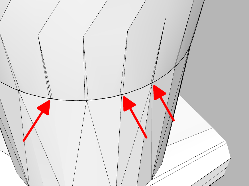
Where did you get the component? It appears to be very poorly modeled with a lot of excess geometry and problems with misaligned circles that will result in very tiny faces even at the larger scale.
I would suggest first remodeling the component so you don't have all this bad geometry.

Do you still have the original .stl file? Will you share it?
-
@dave r said:
What version of SketchUp are you using? Your profile only indicates Free/Make and the Solid Tools aren't available for that version.
One thing that will help in your model is to make the cutter volume larger. Don't be stingy with the geometry.
Where did you get the component? It appears to be very poorly modeled with a lot of excess geometry and problems with misaligned circles that will result in very tiny faces even at the larger scale.
I would suggest first remodeling the component so you don't have all this bad geometry.
[attachment=0:1evq9zzp]<!-- ia0 -->Screenshot - 7_31_2022 , 10_45_39 AM.png<!-- ia0 -->[/attachment:1evq9zzp]Do you still have the original .stl file? Will you share it?
Dear Dave,
Thank you very much for your response,
I'm helping remotely for a partner, the partner have a license and they are using is SU 2021.The STL file is imported directly from the OpenFlexture science project : https://openflexure.org/projects/microscope/build
Here is the direct link to it : https://build.openflexure.org/openflexure-microscope/v6.1.5/optics_picamera_2_rms_f50d13.stlSince it made using OpenSCAD by other team that's skilled in SCAD, I have no skill about OpenSCAD and don't know how to remodeling it. Is there any easier way to workaround?
-
Working with the .stl file is problematic due to the triangulation of all surfaces. If you must work with it in SketchUp you would find it better to import it with Meters as the import units. Also selecting Merge coplanar faces in the Import options will help. Even then it has problems but they will be easier to manage. Seems to me it would be better to use the stl as a reference and create a new, cleaner model of it to avoid problems like those that have been pointed out already. Maybe it's possible to get a 3D DXF file from the original source? Maybe it would have fewer issues. Hard to say from here.
Advertisement


