Another Junji Okubo design - Bouncer S2WT
-
This time a Junji Okubo robot.
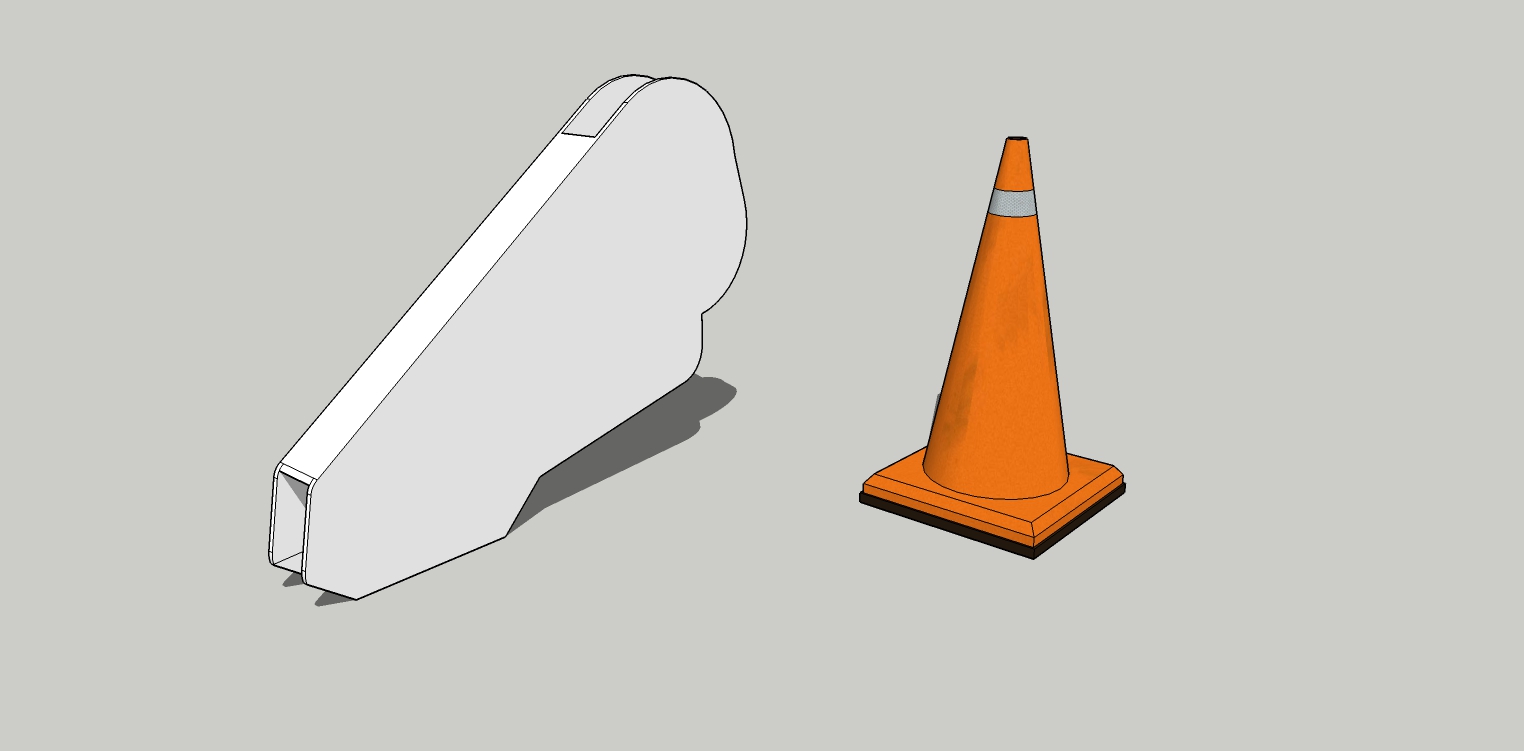
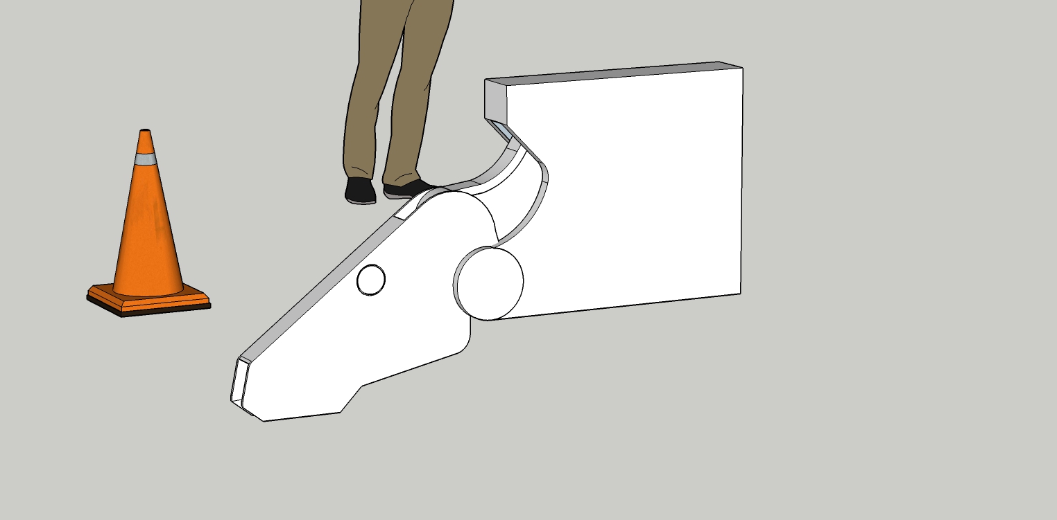
First part of a leg. The traffic cone was to give me an approximation of scale according the original drawing I'm referencing.
-
This is harder than it looks but pretty interesting.
-
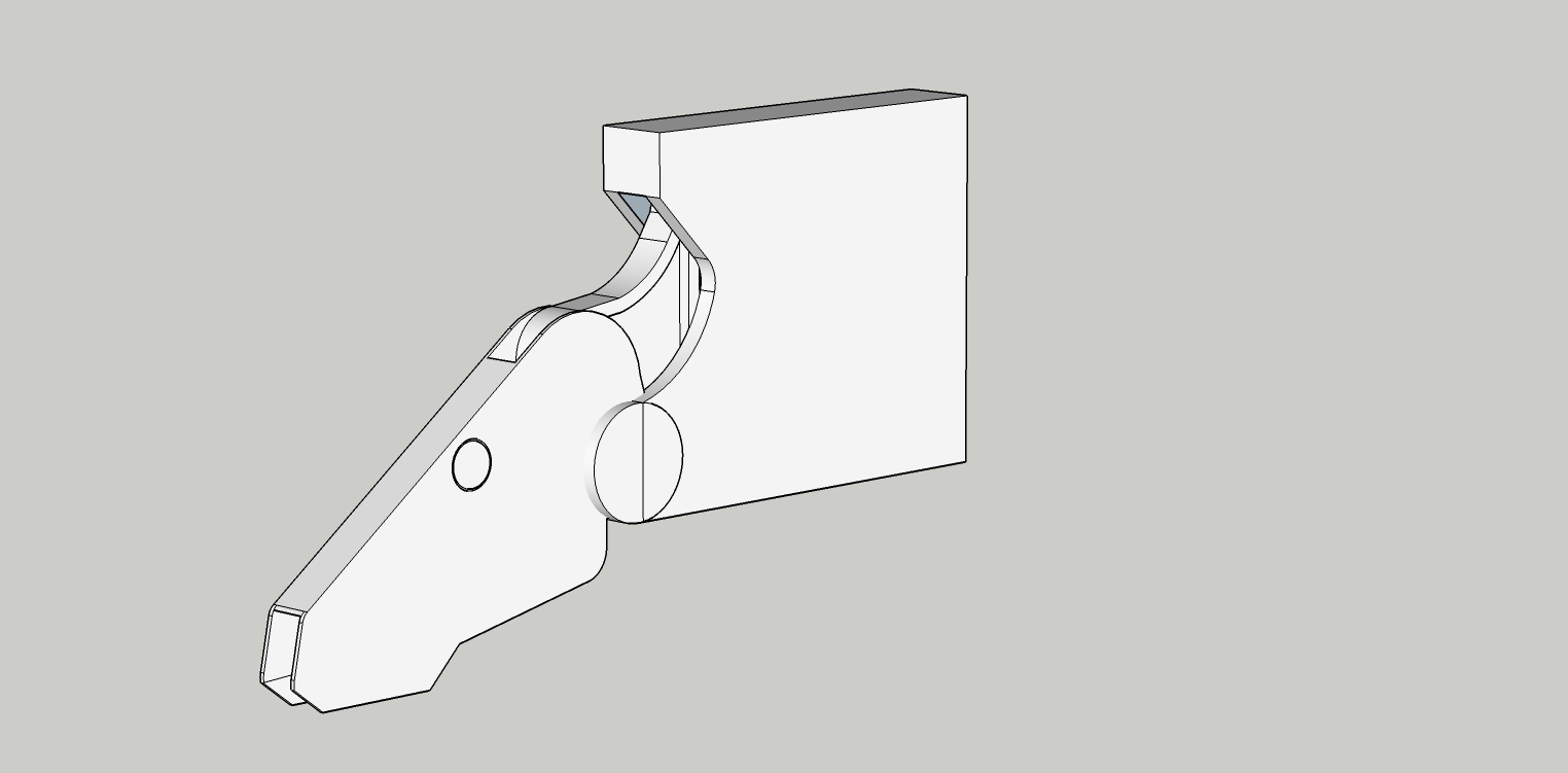
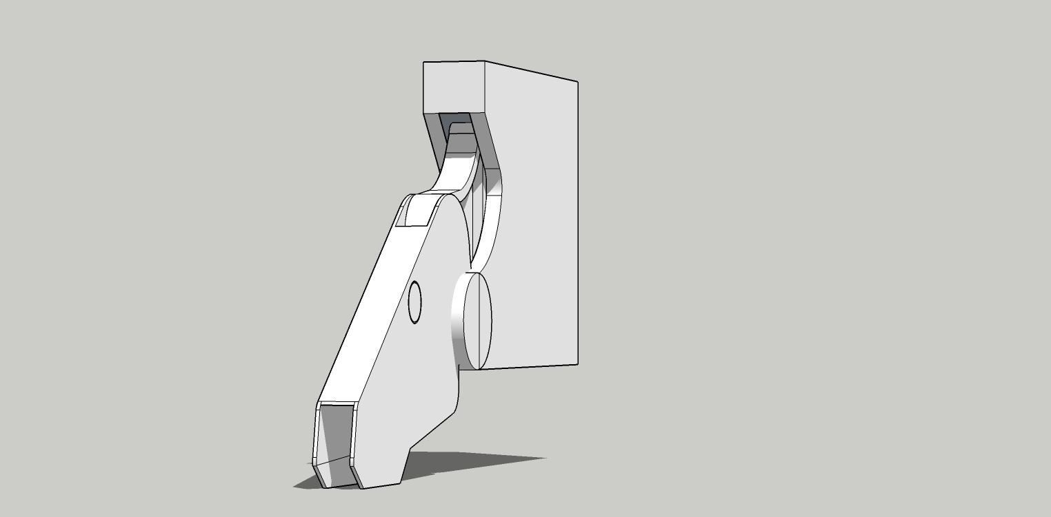
Not much to see, but what I've done is model intersections and clean up.
There is still more forming to be done on this part.
What I can't show is the various groups and components. I've found that the more groups and components I make in all my models, the easier it is to model, edit and intersect lines to form clean models without excessive internal lines. This also optimizes the model file size. Groups and components are made of even the smallest parts.
-
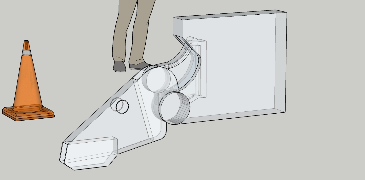
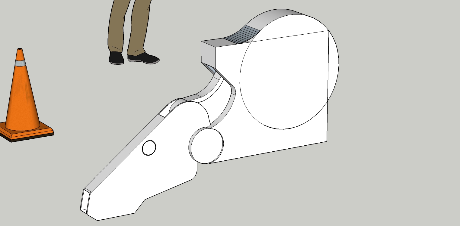
This is to show how I am trying to rough form the next step.
The next post will show the finish result.
-
Will be impressive when i see its twitter

-
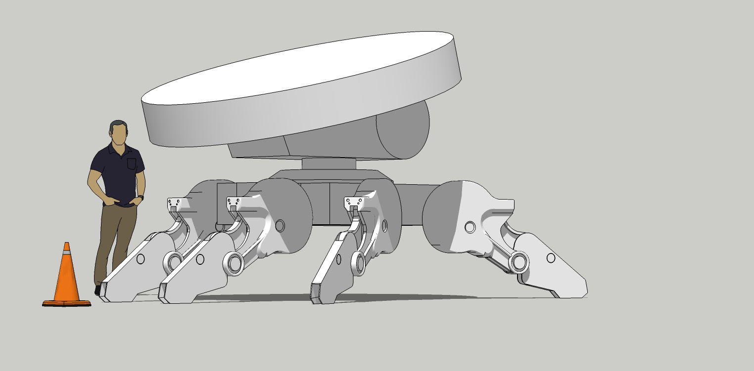
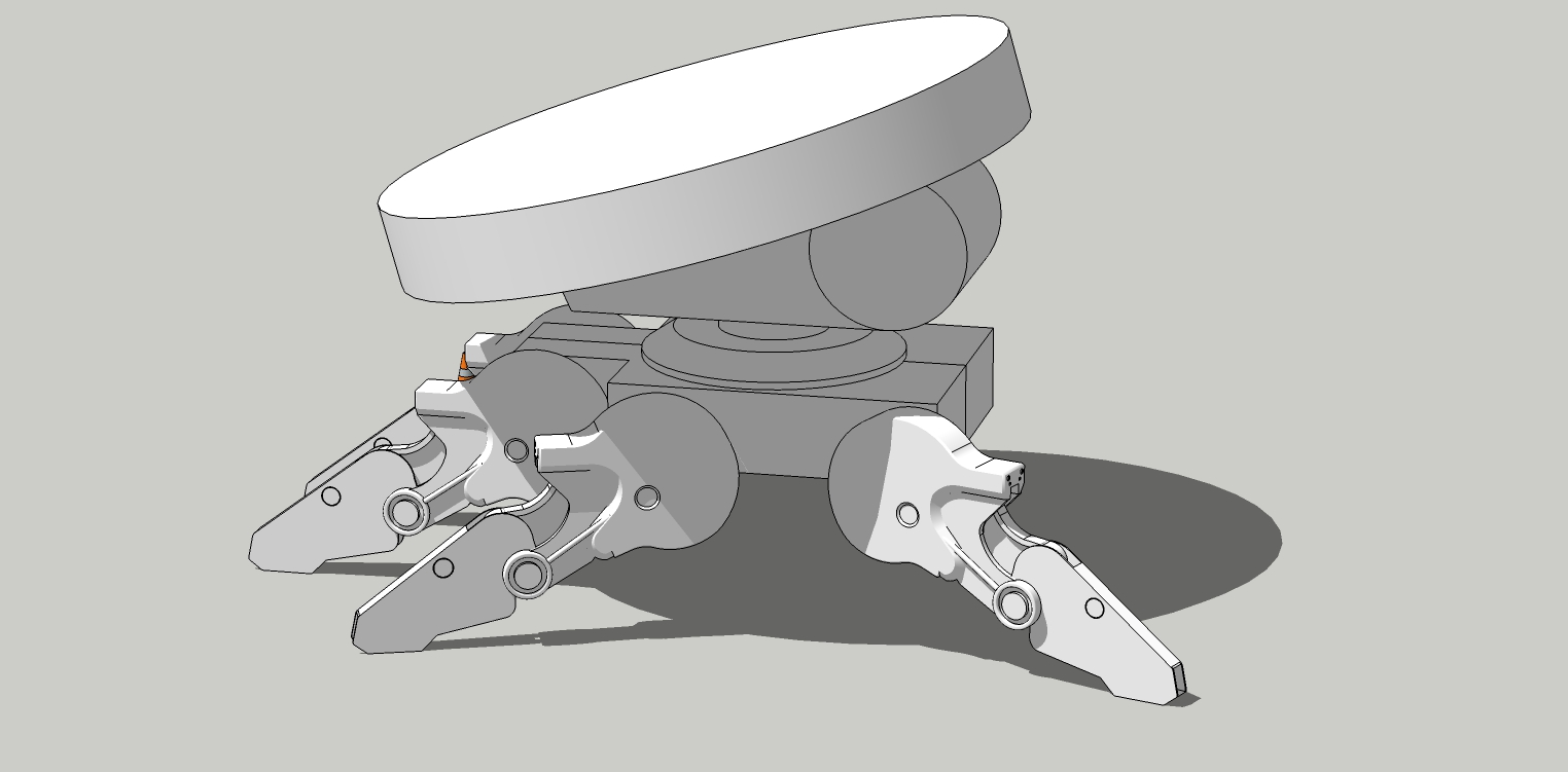
Very rough block out of the overall shape. Not all the legs are shown either.
-
Where do you come up with this stuff!! Guess I am getting too old for this environment.

-
@ntxdave said:
Where do you come up with this stuff!! Guess I am getting too old for this environment.

Honestly? Google search sci-fi. Japanese anime. Futurism. Robots. Spaceships. Etc.
But yeah, random google searches. But I now know who Junji Okubo is and I like his work so I will be doing more of his designs. It was his spaceship design I did the last time.
Deviant Art sci-fi is also a great source.
-
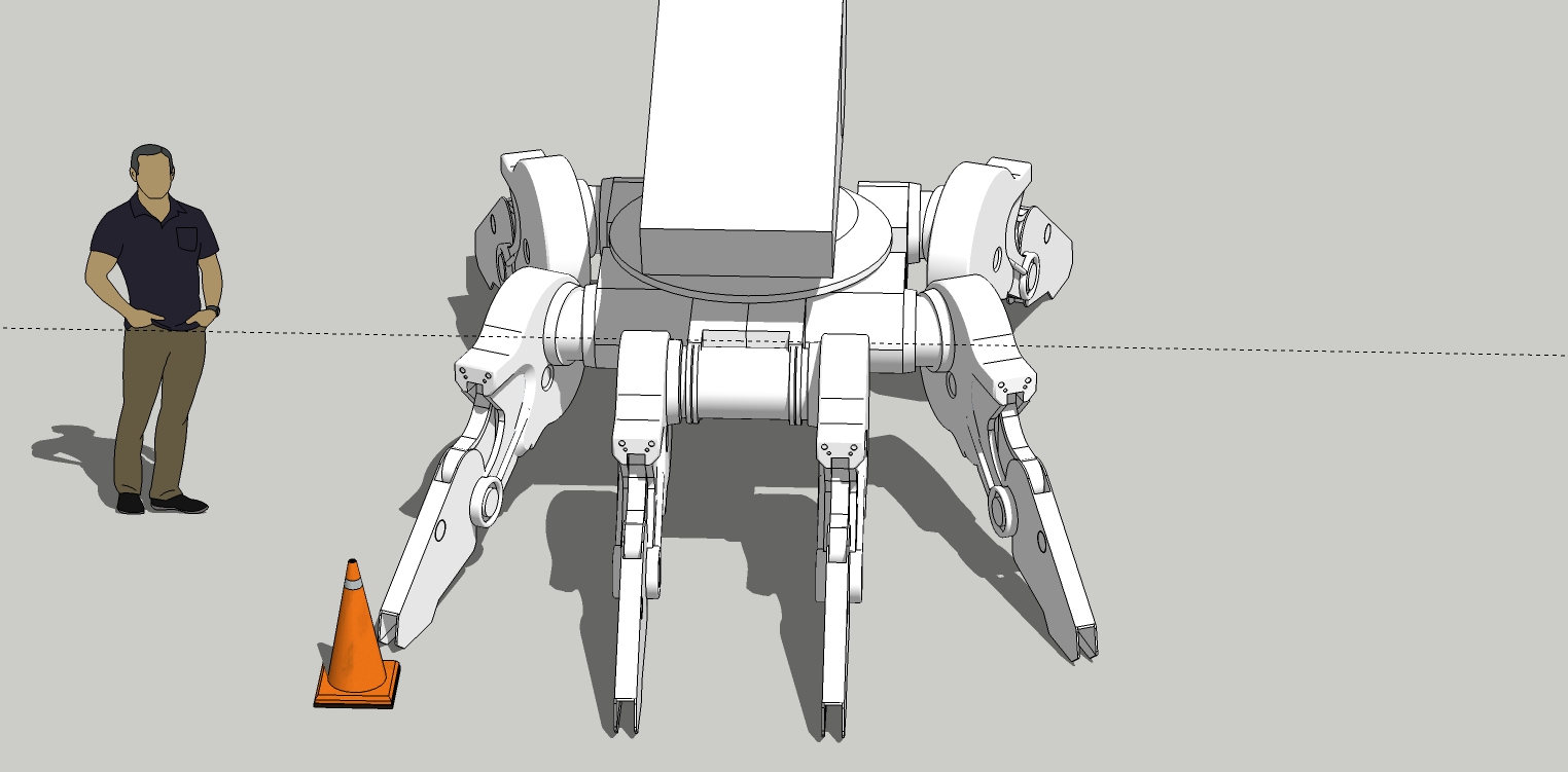
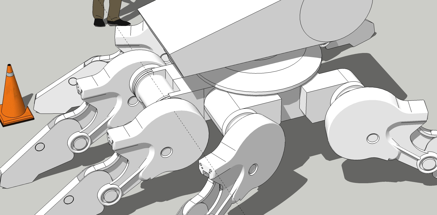
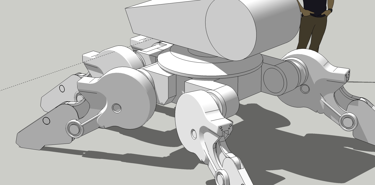
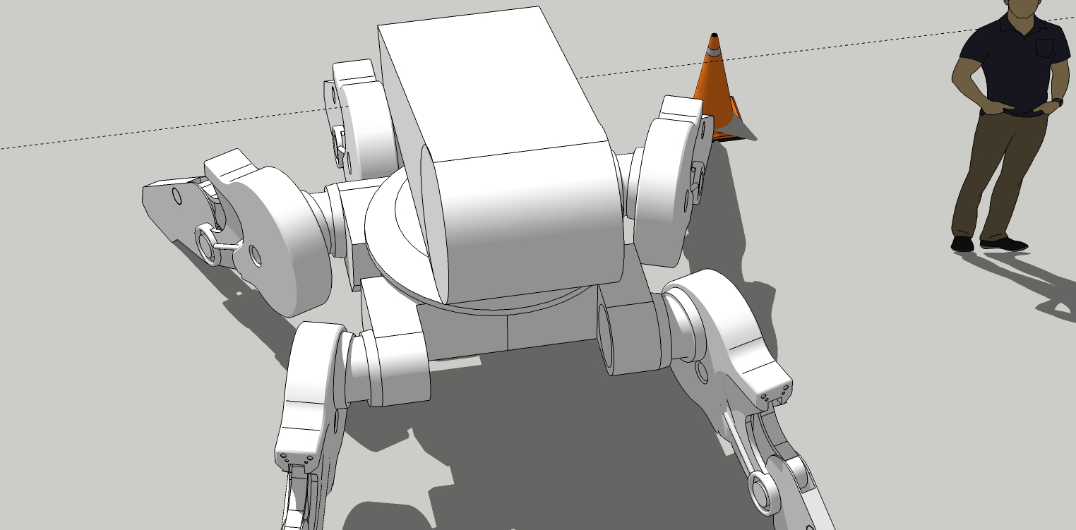
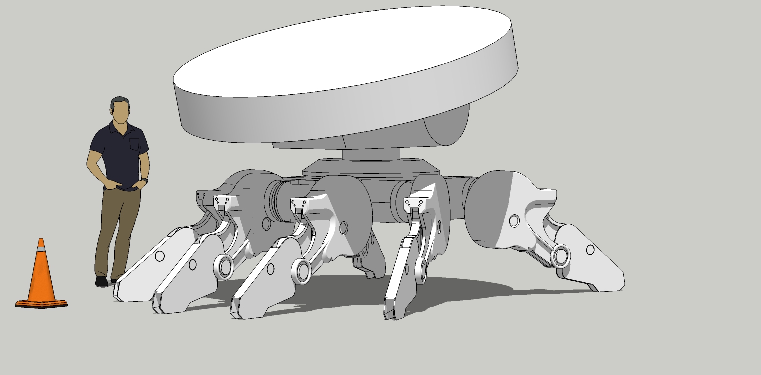
Started detail on the chassis and added all the legs. The chassis is a simple half side component then copied and mirrored. Same with the legs. Got the positions on one side and then move/copied and mirrored.
Simple push/pull cutouts for the chassis and push/pull height match to circles that are the axles for the legs. Nothing has to be perfect. I'm just eyeballing it. (guess-stimating)
The end collars for the axles are slightly conical.
-
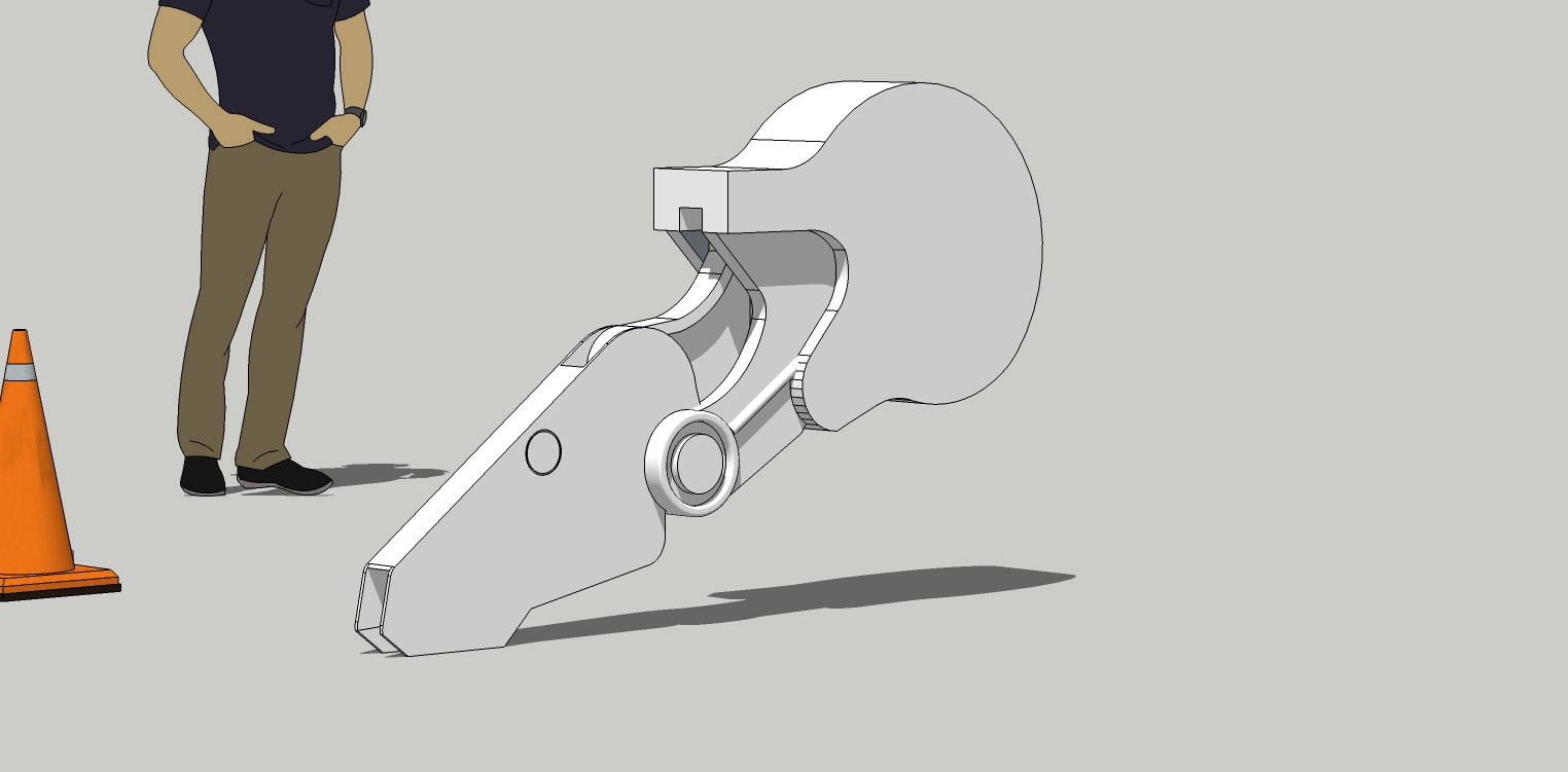
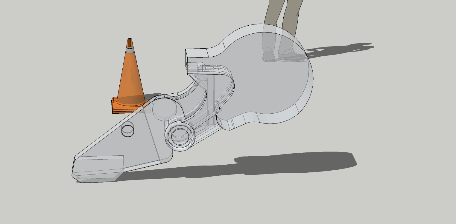
Damn what a pain! This took a lot of fiddling to get right. So deceptively simple. So crazy complex with it's weird compound curves.
Lots and lots of push/pull.
And frankly, I'm only "close" to what the drawing looks like. But close enough. Moving on.
The good part is this is the hardest element of the robot to create.
-
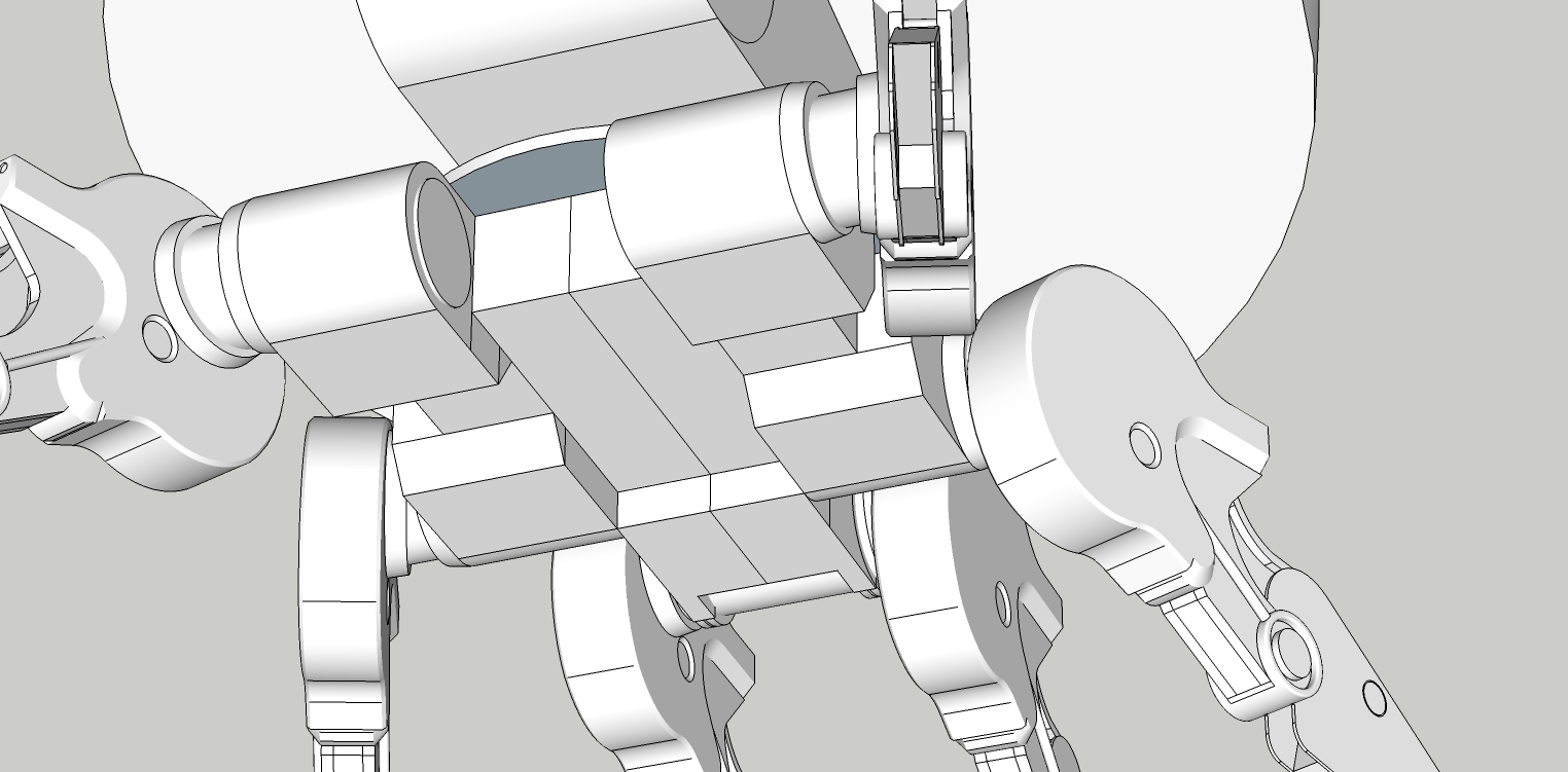
Under-chassis detail. Just more push/pull. It's hard to show so I hope some of you can tell what is going on.
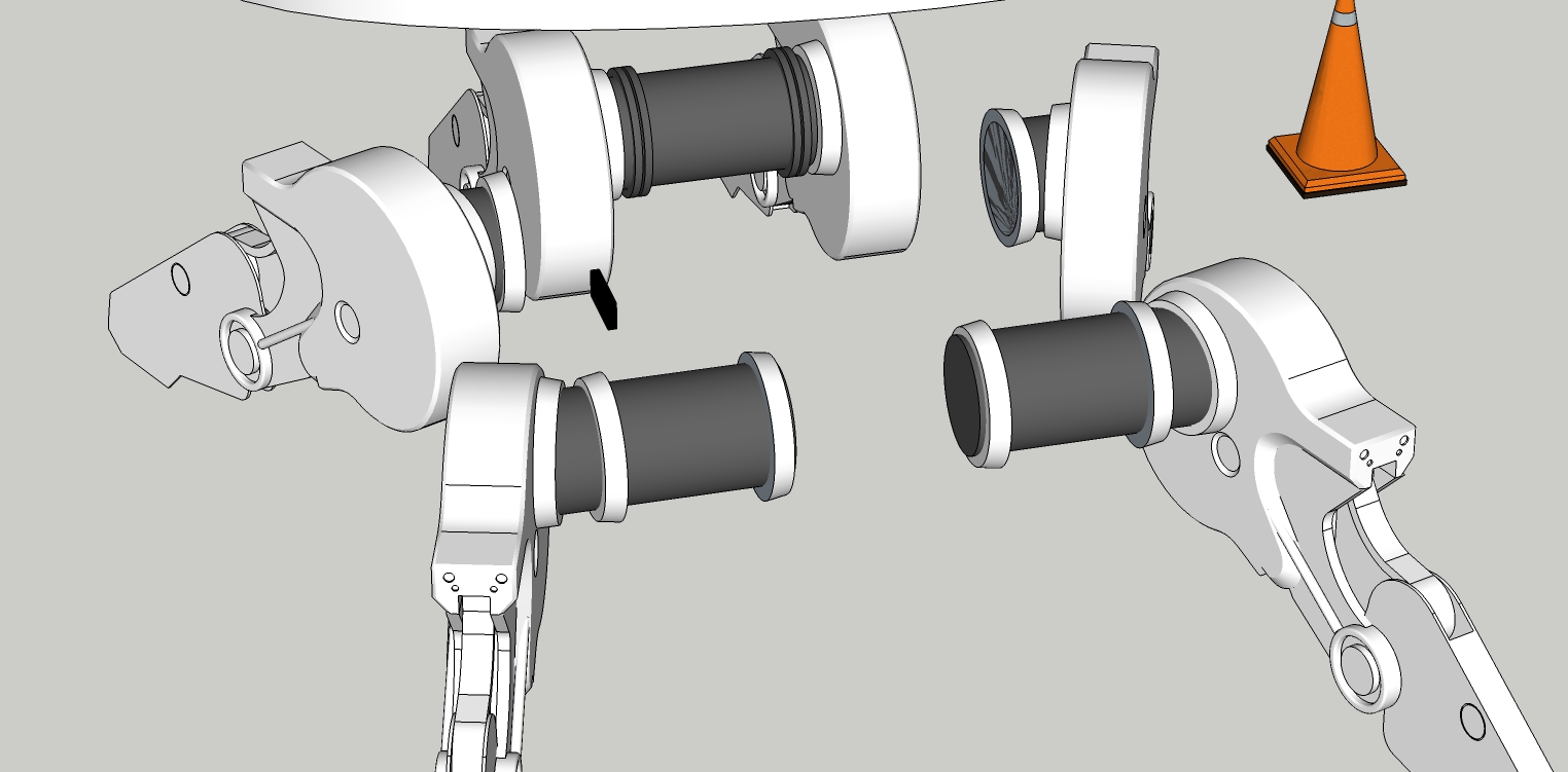
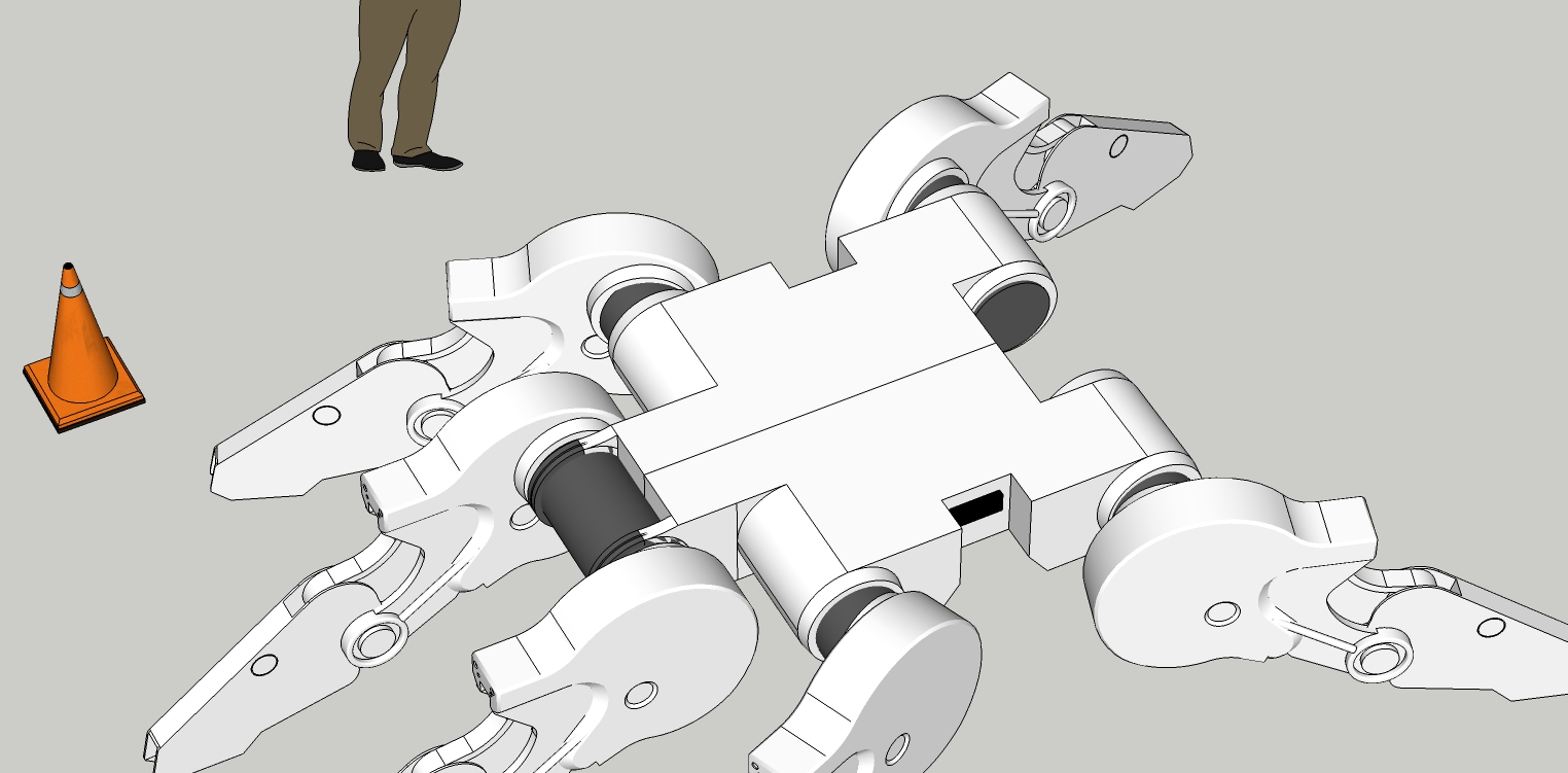
-
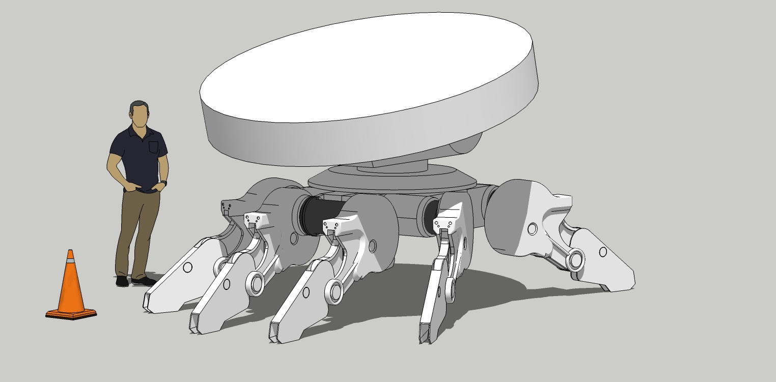
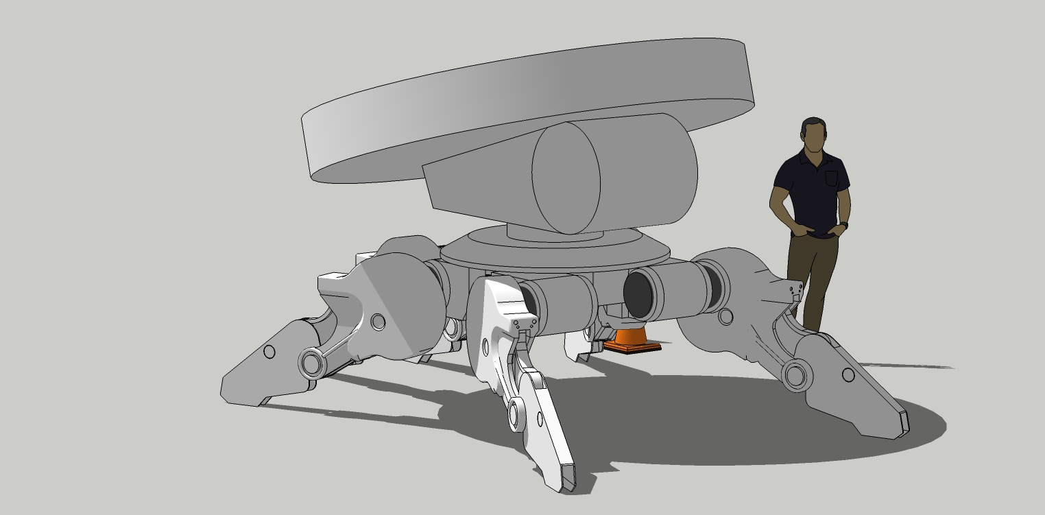
Overview update.
Next will be the middle section that supports the top disk.
-
Blimey, really moved on, it's great mate.


-
@mike amos said:
Blimey, really moved on, it's great mate.


Thanks! I'm feeling inspired with this one.
-
Angle base complete.
Simple circle push/pull and scale bevels with Joint push/pull for the tail lights. Pipe along path for small piping.
Same technique of half component then copy move and mirror.
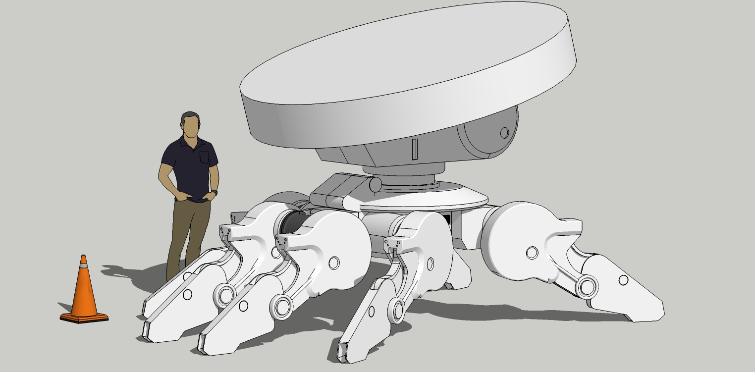
-
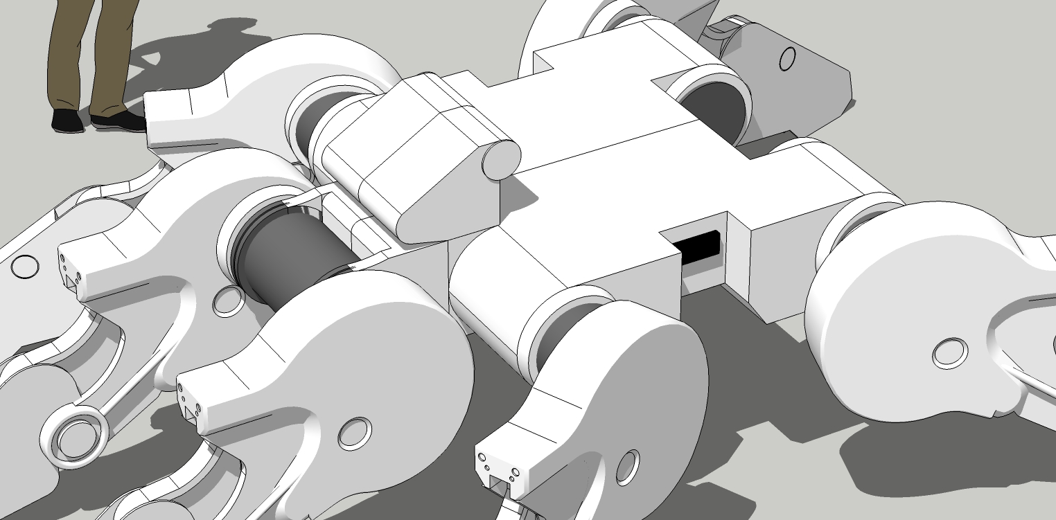
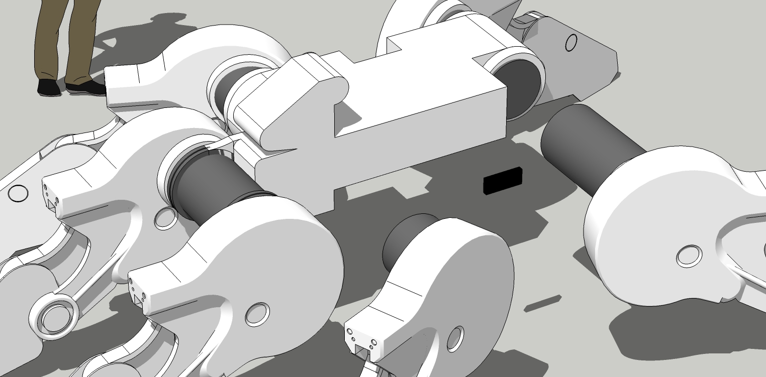
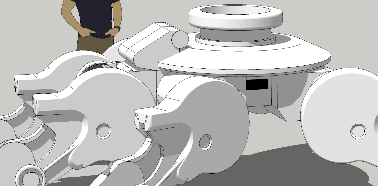
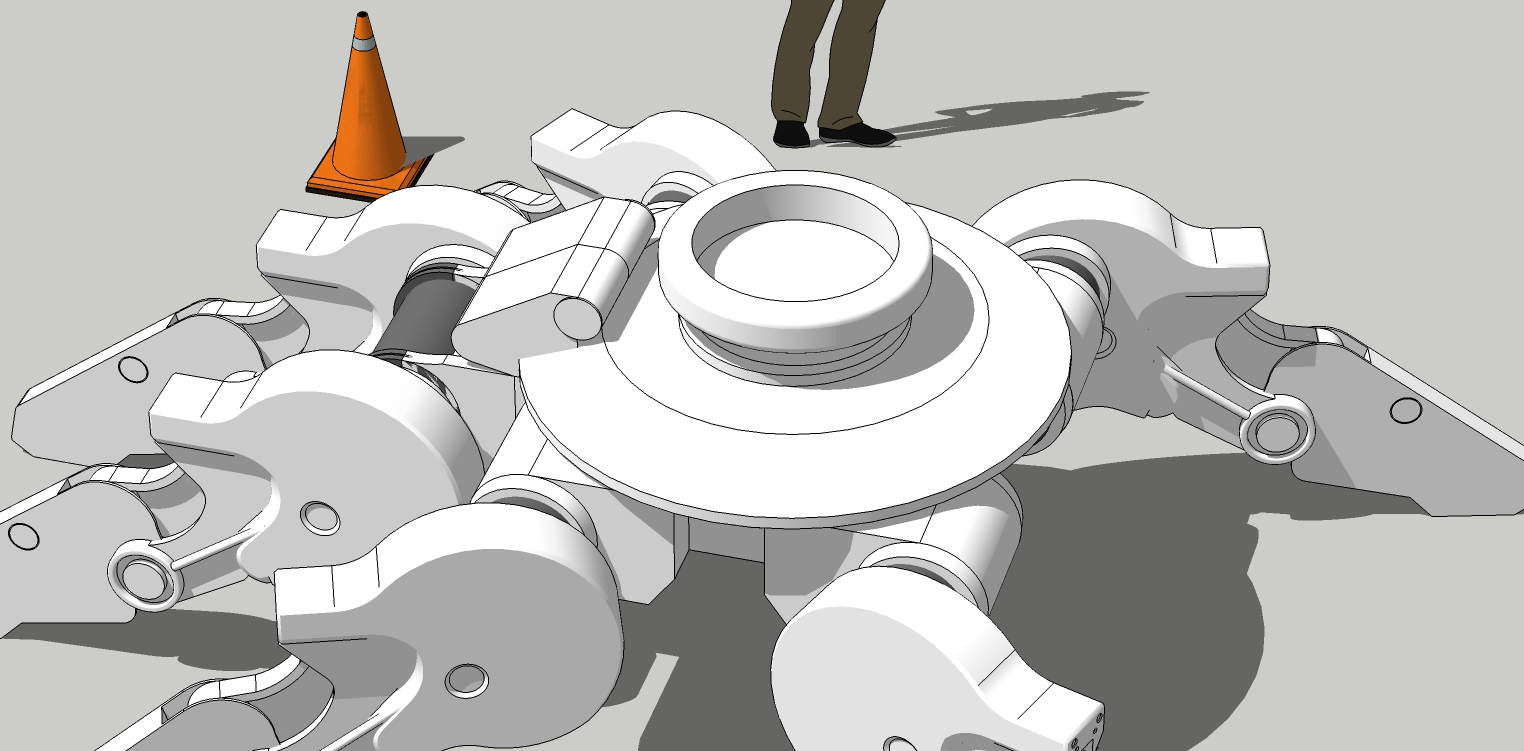
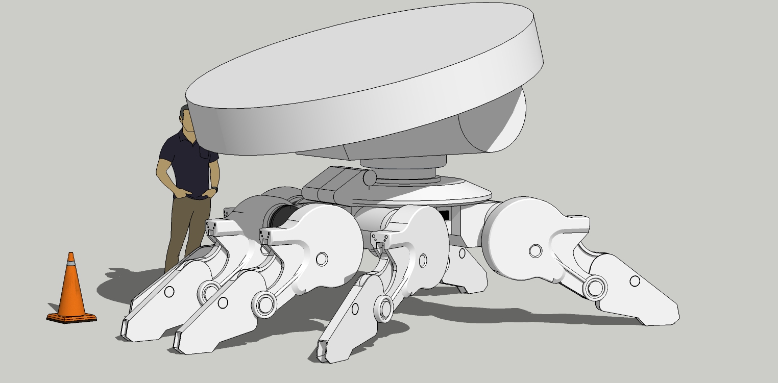
Update. Some final chassis modification and finished support turntable.
Next will be the angled disk base section, just below the disk itself.
Again, more push/pull, and fiddling around moving things.
Used round corner tool on some parts.
-
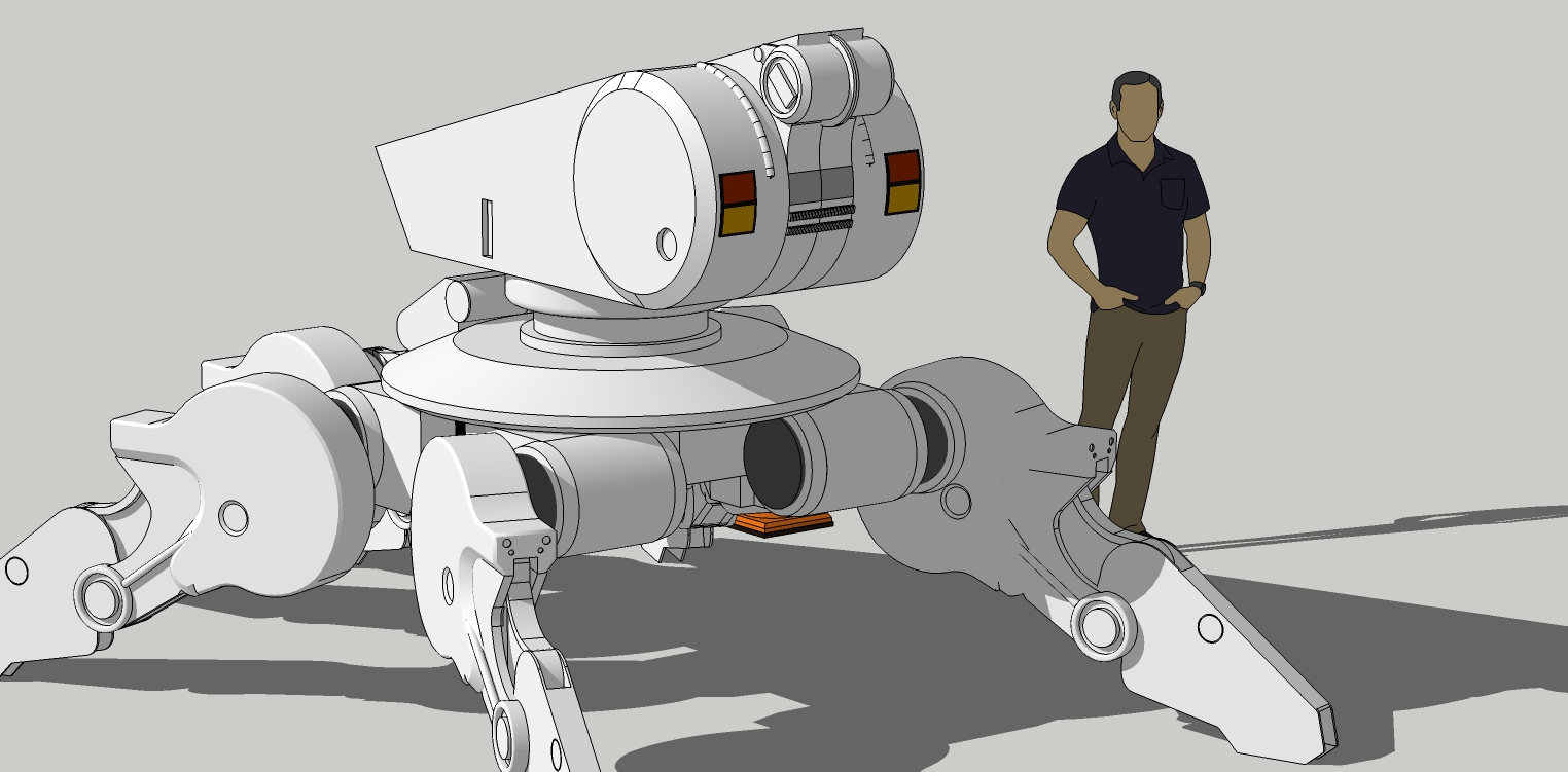
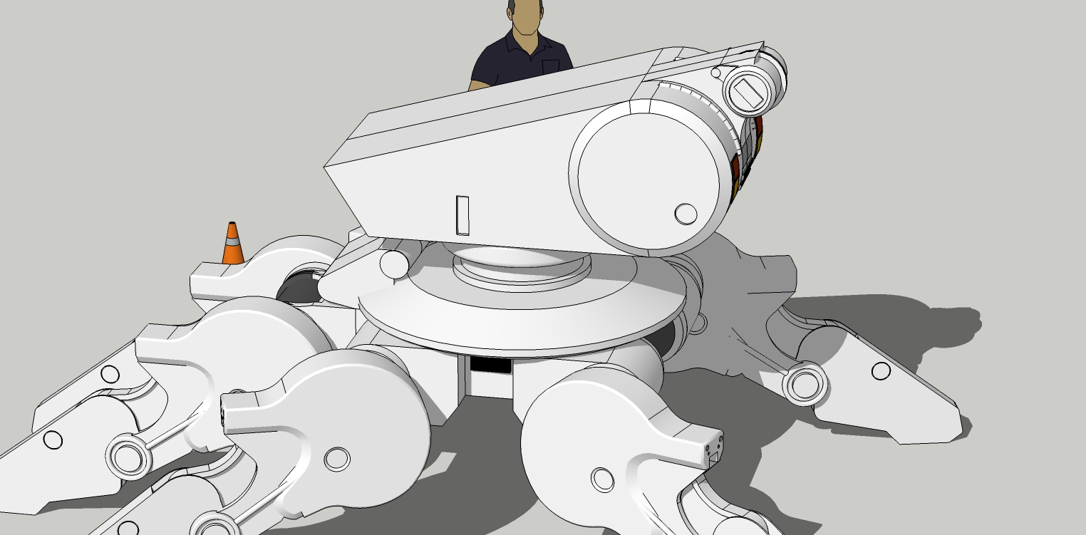
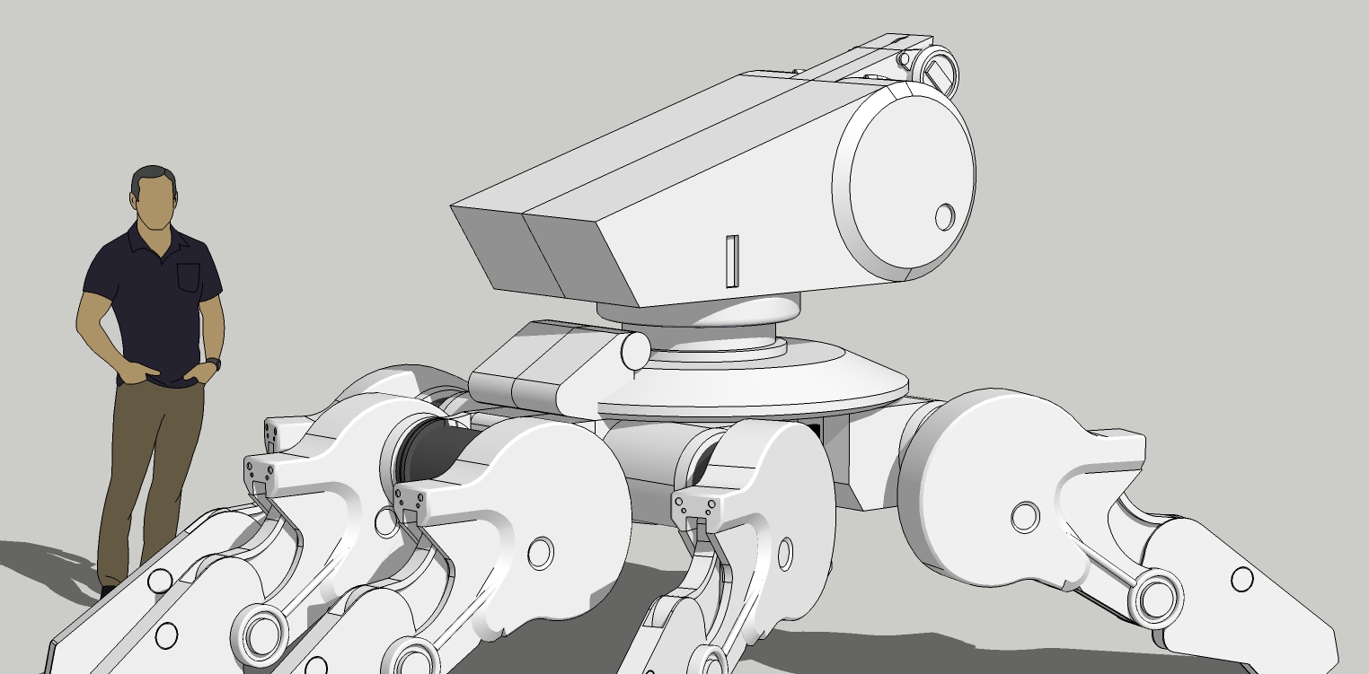
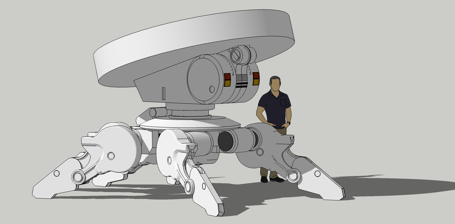
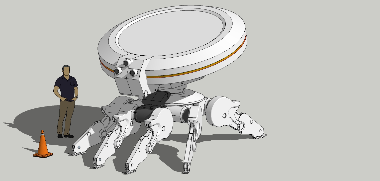
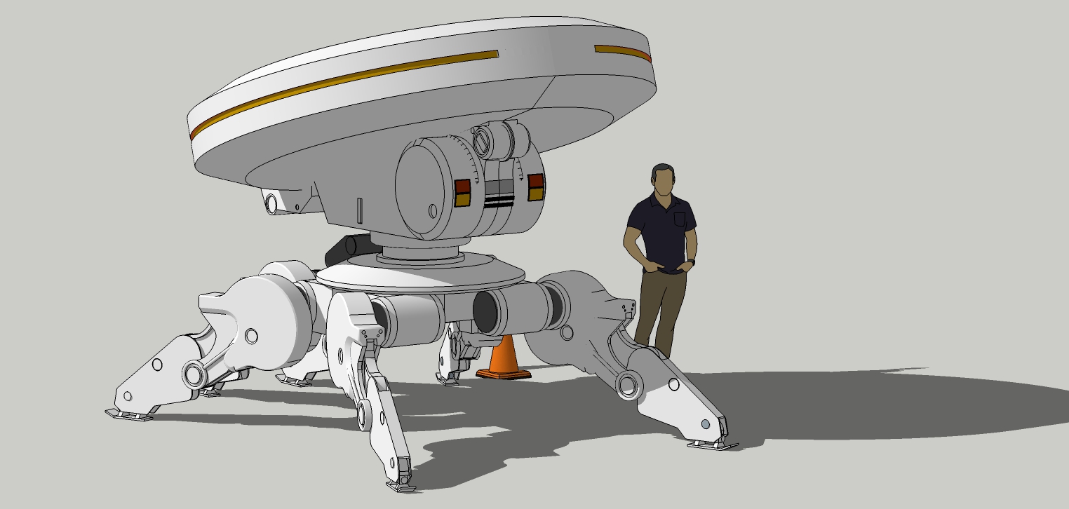
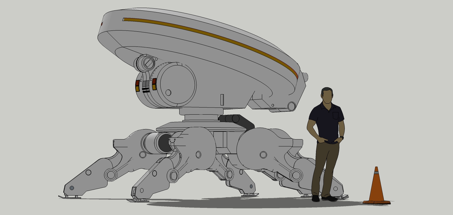
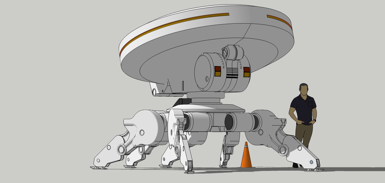
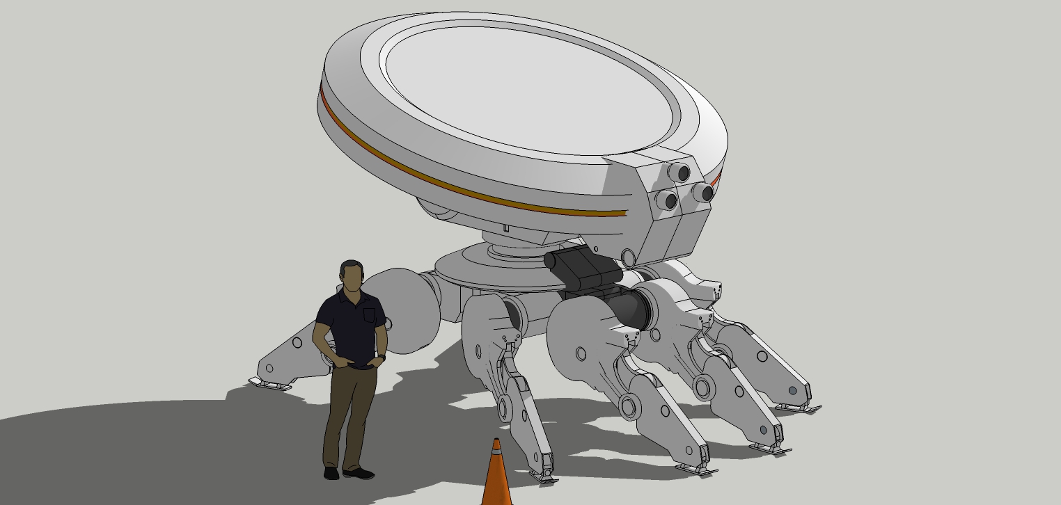
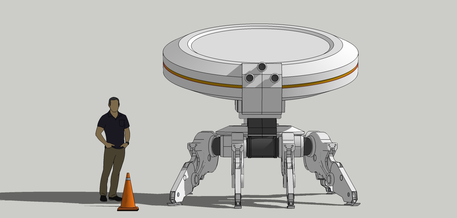
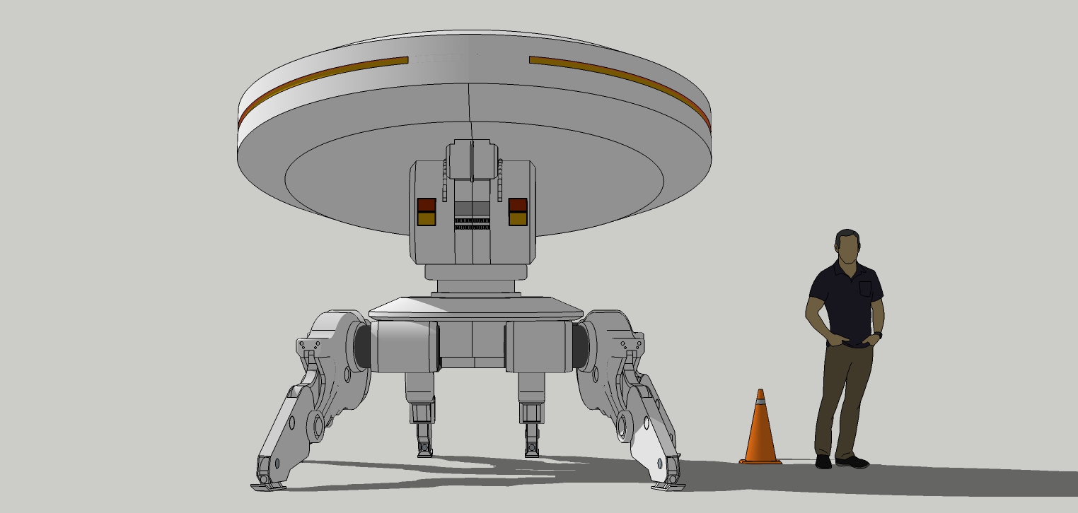
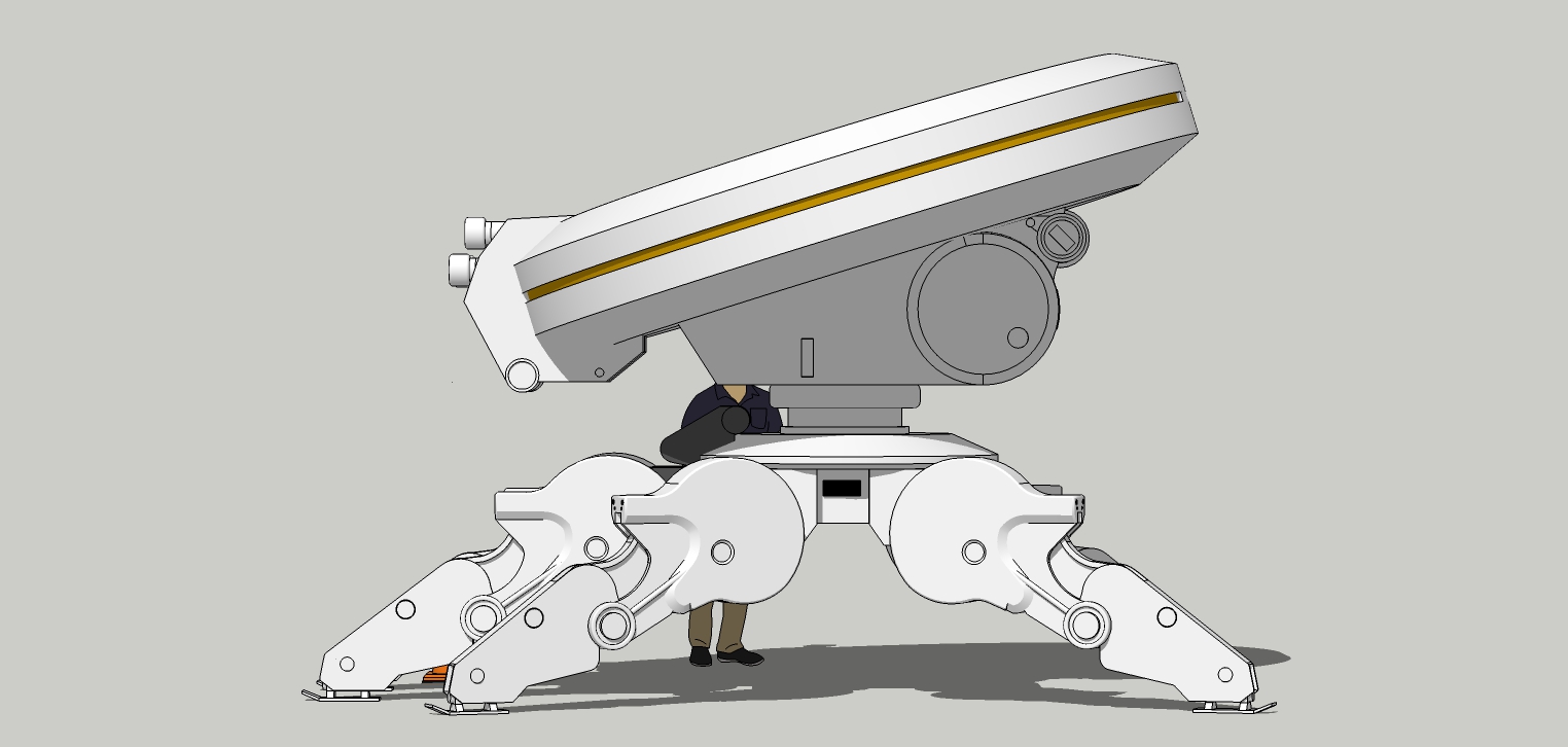
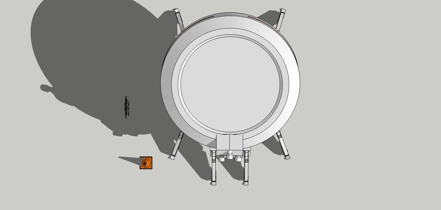
More ridiculous fiddling with the front sensors, but here it is. Finished!
Note the feet added as well. Nothing special. They can be made up as anyone sees fit.
-
... what a cool Design - in this case I´m looking forward to some cool renders, anytime in future


-
Cool adaptation result!

-
Thanks Pilou.

Advertisement


