Newbee can't get a solid
-
Rather than trying to fix your model - which has many tiny errors - can I suggest that you start again in a clean context.
Also at the small size you are modeling I suggest you Scale up x10 - you can always scale back down at the end... Otherwise small facets can fail to form as edge length is limited to 1/1000".Switch on the Axes - they are your ally.
Use View > Mode Monochrome, and ensure that the Style's back-face color is distinctive.
Also toggle View > Hidden Geometry ON/OFF as you go to help see what's happening.First model the central vertical part.
Draw a large flat temporary circle at the origin, making sure that one of its 'nodes' is on an axis - e.g. the red axis.
Make the circle's segment count 24/48/96 etc - so it divisible by several numbers.
Erase the circle's face...Now work in a vertical plane - on and parallel to the red axis.
Draw the vertical-section through the required central part [ignore the horizontal 'pipes' for now].
Give it the required thicknesses for the part.
Note that it's symmetrical about its center-line so you could draw half of it and then group it and copy, then flip it etc...
When it's done, ensure it's one single face, with no divisions or faceless edges left behind.
Now select the flat circle to use as a FollowMe path.
Run FollowMe and pick the cross-section face.
You should now have the entire vertical central part as a solid.
Ensure the form is oriented with no back-faces showing - e.g. reverse one and use the context menu to flip and orient as necessary.
Select it and make it into a temporary group.
That group should report in Entity Info as a solid.Now model the horizontal 'pipes' part.
Put a temporary guideline through the center of the central part's group, parallel to the red axis.
Draw a large circle centered on that with its axis parallel to the guideline, away from the rest, to use as a path with FollowMe later.
Again, ensure that its 'nodes' is on an axis - e.g. the green or blue axis.
It's segment count should be the same as the first part's path.
Erase the circle's face.
Now draw the long-section through the whole 'pipe'.
Ignore the 'central slot' in it for now...
As with the first part, it is symmetrical, so you only need draw a half and copy/flip etc.
When you have a single face made, use the preselected circle path with FollowMe and that long-section face to form the 'pipe' shape.
Ensure the form is oriented with no back-faces showing - e.g. reverse one and use the context menu to flip and orient as necessary.
Select it and make it into a temporary group.
That group should report in Entity Info as a solid.Make a grouped block the size of the 'central slot' and position it accurately through the center of the 'pipe'.
Edit the pipe-block.
Use View > Component Edit > Hide Rest of Model > ON to see what you are doing.
Select all.
Context-menu to Intersect with model.
There should now be cut marks where the pipe intersects the vertical part and the 'slot'.
Exit the edit.
Edit the Vertical part and repeat the intersection.
There should now be cut marks where the pipe intersects the vertical part.
Exit the edit.
Now re-edit each of the two parts' groups, and tidy up the intersecting geometry interfaces at the 'cuts marks'.
Either delete unwanted faces or select/Edit>Cut them and the paste in the edit of the 'other' part - this way you
Delete the unwanted slot-group, guidelines and circle paths.
Select the pipe-block and Edit>Cut, immediately edit the vertical part's group and Edit>PasteInPlace.
Explode the pipe-group so that it merges with the main part.The selected group should now report as 'solid' in Entity info.
If you scaled it, now scale back down again...
-
Thanks for all the comments. It has opened my eyes to things I was not aware of before. I will give it a go trying to follow TIG's instructions but, like I said, I am not a pro and this was a see-if-I-can-do-it thing. I imagine this is going to be too much for me to learn.
-
Some messy indeed!

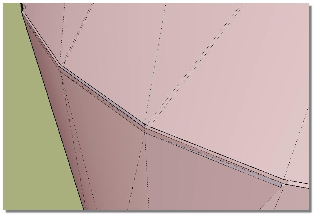
You must be very precise !All must be very clean and closed!
Enable Display / Hidden Geometry and make some many zoom everywhere for be sure!
Use Join Push Pull by fredo for make thickness on simple volumes or surfaces!

-
Using followme makes sense to me since the end result would be solid. But I can't figure out how to make a profile that I can use with followme.
-
Some idea

Enable Display X Ray, Hidden GeometryPush Pull
Scale + CTRL Perimeter
Triple click =select all
Move + CTRL * 3
etc...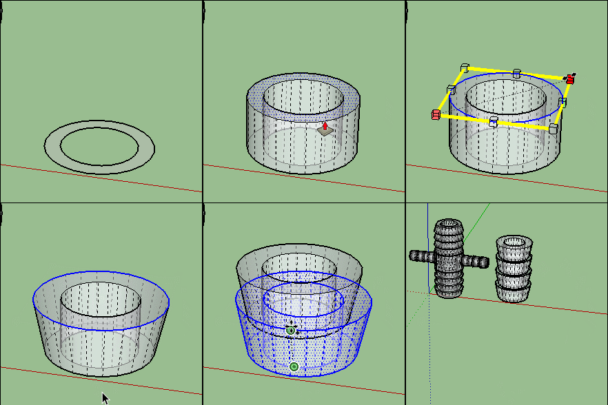
-
Don't be frightened of it, there is no magic involved.
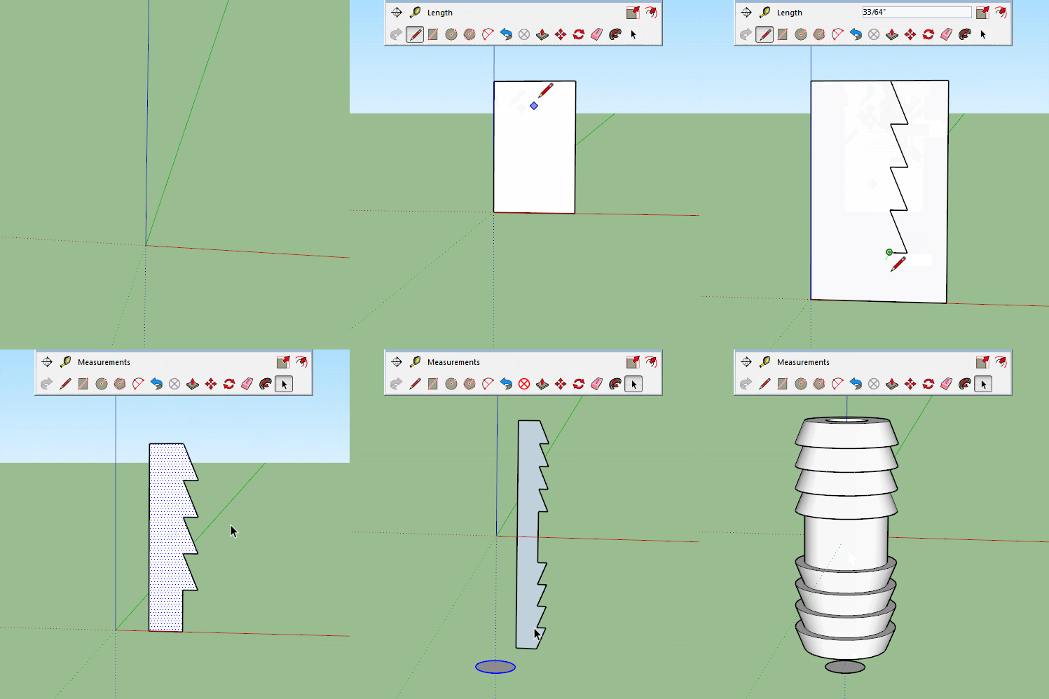
Everything in SU is just edges and faces, so draw the profile at right angles to the path follow me will do its job.
Obviously this isn't accurate, but it shows the process. You can measure and add guides as much as you need but it all comes down to a simple set of edges that form a face that can make the shape you want when swept around a circle. (or other shape for that matter)
-
Wow, thanks for the video. I DID IT!!!
-
Sorry to the trouble. The vertical section went great. I am now doing the same with the horizontal section but the ends aren't closing after the follow me. I read some where that if the object was too small the ends might not close so I expanded it double and it still is not closing. What am I doing wrong?
-
When we talk about scaling up to edit we really mean 10, 100 or 1000 times bigger, not double.
If you scale yours up by 10 the face will form.
Or use the Dave Method as described here.
https://sketchucation.com/forums/viewtopic.php?f=18&t=68150 -
Well Mine is simple or so they tell me . . I made the part on the axis and thought that should make it easy . . Wrong . . Rotate flipped the part over and Follow Me makes a BIG mess out of it . .wants to twist one end to the other like a pretzel
-
@just4lynne said:
Well Mine is simple or so they tell me...
A month ago you were told on the other forum that you haven't properly set up the model for Follow Me. Plenty of help was offered. There's either no Follow Me path or no profile. Unfortunately you haven't made it clear what it is you are trying to model so it's impossible to tell which is missing.
-
Trimble are taking advantage of the new technology that has been made available in the last 2 years to weed out people using the software without a license. This is the proof of concept test, they link into the transmission from the vaccine, if they don't find it they disable certain features, follow me for example.
-
@dave r said:
@just4lynne said:
Well Mine is simple or so they tell me...
A month ago you were told on the other forum that you haven't properly set up the model for Follow Me. Plenty of help was offered. There's either no Follow Me path or no profile. Unfortunately you haven't made it clear what it is you are trying to model so it's impossible to tell which is missing.
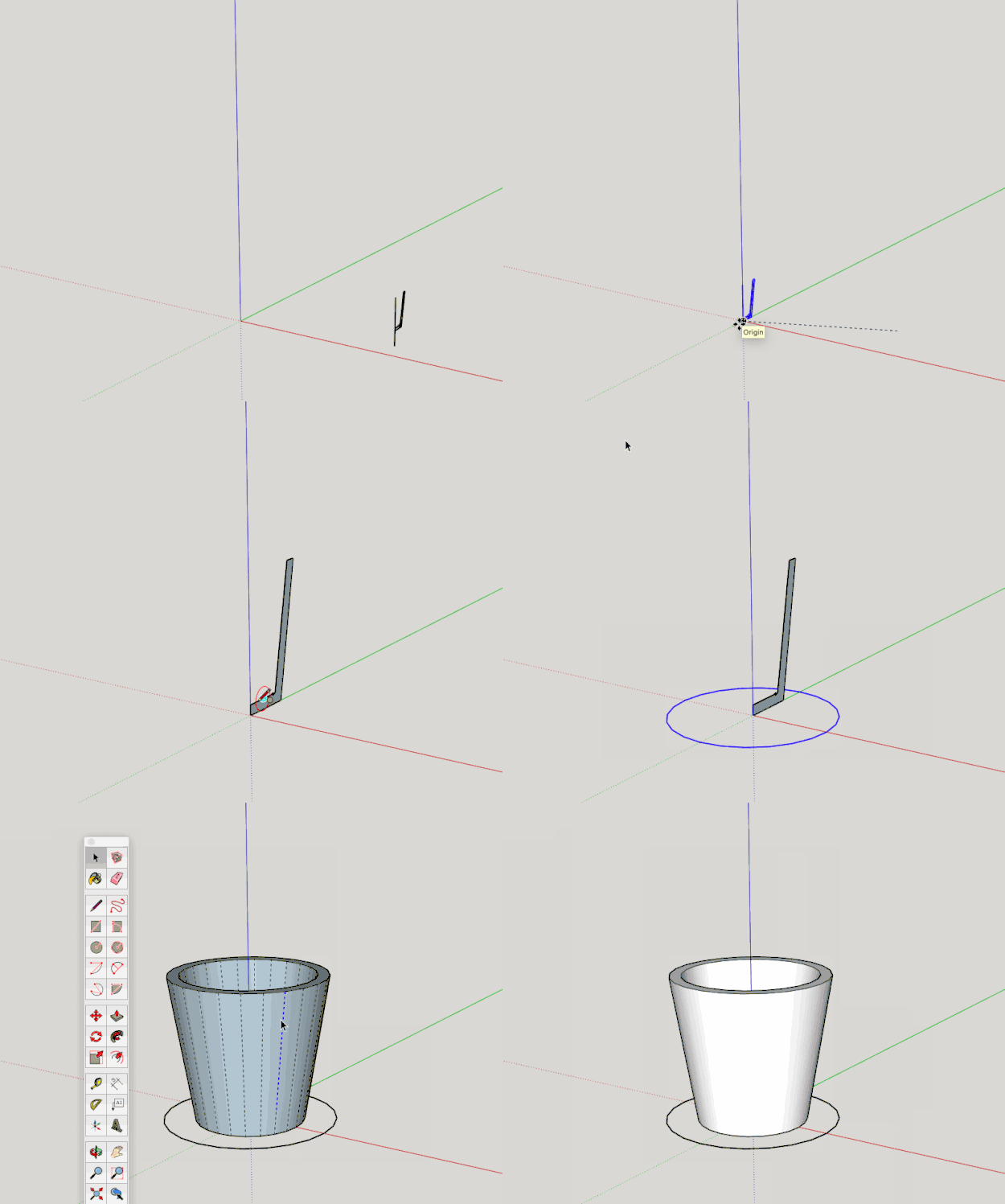
Well I thought it was set up right . . There are rules to set it up for Follow me ? what are they ? Never seen any thing saying do it this way . . Only thing some one said to me is it has to be on the edge of the 3D Printing Box So I made the Edge right on the side of the Box . . And It just needs rotated on the edge of the box 180 Degrees ( was flipped 180 degrees and that is why it is outside the box now ) Flat part made into a lump or a hill for some ones game. . laid out and scaled for their game board . . I have a short video showing how a glass was made and so I tried to do the same thing ! . . and this is a new item to be done for a friend . . So I don't know where this month ago came from . .
-
@unknownuser said:
I have a short video showing how a glass was made and so I tried to do the same thing !
Except you left out the path in your model. There's nothing for Follow Me to follow.
@unknownuser said:
and this is a new item to be done for a friend . . So I don't know where this month ago came from
Seriously? You posted the same SketchUp file 30 days ago here:
https://forums.sketchup.com/t/where-am-i-doing-it-wrong/180294
After Aaron and pbacot tried to help you, you apparently ignored them. -
Evidently...
-
Obviously Dave your are posting leftist communist lies. The alternate facts prove otherwise.
-
@just4lynne said:
. . I have a short video showing how a glass was made and so I tried to do the same thing ! . . and this is a new item to be done for a friend . . So I don't know where this month ago came from . .
If you go to the thread at SketchUp Community, we showed that a circular path is needed You need to draw a circle for the path.
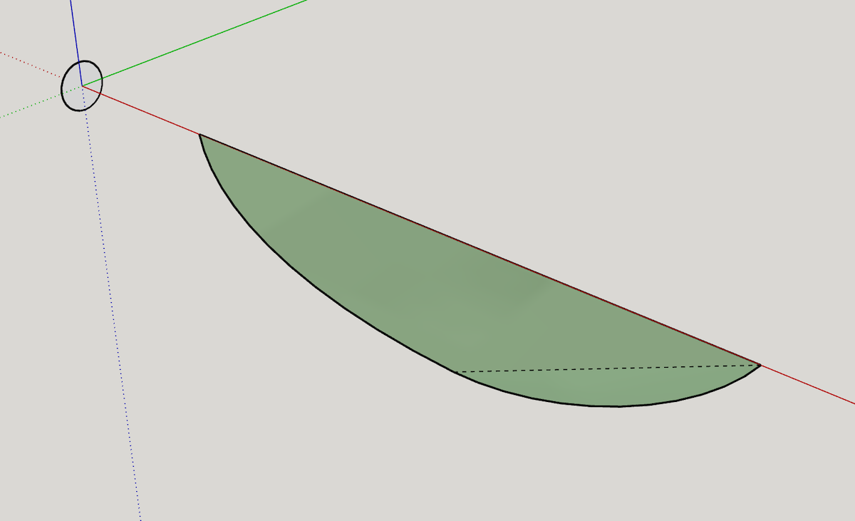
However the file you posted here actually is different. There's an extra edge in the surface.Turn on hidden geometry. The surface is really made of two faces that are not coplanar and they will not both extrude using followme at one time. It would be better to start with an object that has ONE face.
-
Wish I had saved the one which was made before I tried to make it rotate . . Now I get to re draw it again there is a guide that seems to have been saved in the part . . And it is where it like to bend there . . So How did you get the circle drawn at the Axis ?
-
@just4lynne said:
...So How did you get the circle drawn at the Axis ?
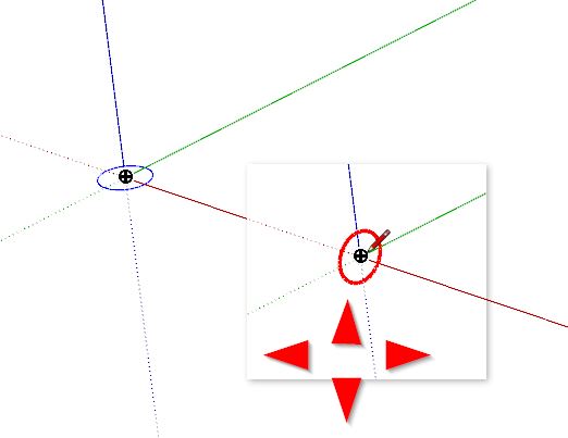
Hi - select the circle tool and place your cursor near the origin point. The Cursor will now snap to the origin.
Now please "play" with the 4 cursor arrows on your keyboard. The circle tool will then show up in your desired orintation color (for example red)
Advertisement


