sketchucation logo sketchucation
    • 登入
    Oops, your profile's looking a bit empty! To help us tailor your experience, please fill in key details like your SketchUp version, skill level, operating system, and more. Update and save your info on your profile page today!
    🔌 Smart Spline | Fluid way to handle splines for furniture design and complex structures. Download

    Medeek Electrical

    已排程 已置頂 已鎖定 已移動 Plugins
    205 貼文 6 Posters 226.1k 瀏覽 5 Watching
    正在載入更多貼文
    • 從舊到新
    • 從新到舊
    • 最多點贊
    回覆
    • 在新貼文中回覆
    登入後回覆
    此主題已被刪除。只有擁有主題管理權限的使用者可以查看。
    • D 離線
      db11
      最後由 編輯

      Nathaniel —

      Any thought of creating an auto-generating mode for the wiring module?

      I imagine it working something like this:

      1. Select start device (set startType)
      2. Select end device (set endType)
      3. Resolve path type:
      • outlet to outlet
      • hot wire to switch box/junction box
      • switch to fixture
      • fixture to fixture
      • etc..
      1. lookup presets for device heights / wire path height / curve radius etc.
      2. create wire path based on presets / rules
      3. generate wire geometry

      (The logic would be a little more complex for resolving 3-way switch to fixture paths, but doable)

      Of course the resulting paths would be editable using the same mode as you've shown.

      A similar approach could then be used for the HVAC module, using the appropriate rules and presets (including room volumes, desired CFM, ACH etc) to set duct sizes per trunk/branch etc.

      Not to add to your substantial to-do list(!), but the value of auto-generated wiring / plumbing / HVAC runs would be huge. This function doesn't have to be perfect or encompass every possible use case — even if the auto generating only achieves 60% of the end result and the rest need to be edited, it's still a huge reduction of modelling time/effort.

      Interested in your thoughts on this.

      1 條回覆 最後回覆 回覆 引用 0
      • medeekM 離線
        medeek
        最後由 編輯

        @db11

        In theory what you have described seems like a workable solution and possibly a valuable feature that could be added to the plugin.

        However, there are a few difficulties with implementing this in practice. Typically two devices are separated from each other (possibly in different walls) in the X-Y plane (let's disregard the Z axis for now). The simplest path between any two devices based on their location and rotation would be one of three cases: straight line, L-shaped path, S-shaped path (this assumes orthogonal walls of course).

        It would be easy enough to enable some sort of logic to determine which of these three options is the correct path (path finding logic) between any two devices. Adding the height difference further complicates things but that could also be factored in and programmed.

        The problem I see is that except for the simplest of cases the path determined by the algorithm will rarely coincide with what you the designer or electrical contractor would actually do in real life. I'm going to say 95% of the time the path will need significant adjustment so that the wires land properly (centered) inside of the walls.

        The user would probably find this feature more frustrating than useful, but I could be wrong.

        P.S.
        Now, if the algorithm was even smarter and could somehow take into account the walls, ceilings and floors within the model and also use this information in generating the path then I could see the light at the end of the tunnel on this one. I will have to give this some more thought...

        Nathaniel P. Wilkerson PE
        Medeek Engineering Inc
        design.medeek.com

        1 條回覆 最後回覆 回覆 引用 0
        • medeekM 離線
          medeek
          最後由 編輯

          Version 1.2.2 - 10.16.2020

          • Added a "2d Symbols Only" parameter into the General tab of the Global Settings.
          • Enabled the "2d Symbols Only" mode for the following electrical elements: Outlets, Switches.

          http://design.medeek.com/resources/electricalplugin/images/elec_su214_800.jpg

          http://design.medeek.com/resources/electricalplugin/images/elec_su213_800.jpg

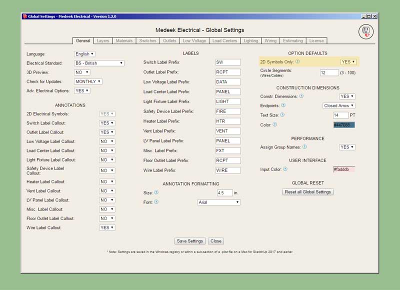
          Yet another update per customer requests. A number of users only want to use the plugin to show the 2D electrical symbols rather than drawing the 3D electrical components (and the symbols). (Technically one could achieve pretty much the same result by turning off the electrical rough and finish layers.)

          The new 2D symbols only mode will allow this mode wherein only the 2D symbols are drawn. Note, that I have only enabled this feature for outlets and switches thus far and I will need to extend that functionality to all other electrical elements (ie. fans, data outlets, floor outlets, panels etc...)

          The nice thing about this bimodal system is that all of the regular data is being stored for each electrical component in the model (attribute library) so one can switch between modes mid-stream without any problems if necessary.

          Nathaniel P. Wilkerson PE
          Medeek Engineering Inc
          design.medeek.com

          1 條回覆 最後回覆 回覆 引用 0
          • medeekM 離線
            medeek
            最後由 編輯

            Similar to the estimator found in the Wall plugin the user will be able to select "All" or a selection of assemblies to run the estimator on:

            https://aws1.discourse-cdn.com/sketchup/original/3X/c/1/c171afbeaf02208ed12b9aca04c89d1fceaaa8dc.jpeg

            The non-Medeek wall and roof assemblies will also be selectable since the Electrical plugin also works with non-Medeek walls, roofs etc...

            I don't feel like it is necessary to break the listings into the assemblies they are part of however I will include a column in each table which lists the main assembly the electrical component is found in, this should prove useful to some.

            There are a lot of little details with regards to different electrical components (ie. outlets, switches, panels etc...) Each type of electrical component has unique characteristics, all of this data needs to be output by the Electrical Estimator, it will probably take me a few days to assemble this new module.

            Once it is complete it will make this plugin a much more useful tool.

            P.S. I think it would be also quite useful at some point to incorporate a price database that works with the estimating module. This separate database would be referenced to determine the price, vendor etc... for a given electrical component. Additionally, the list of materials could then be conveniently broken into separate purchase orders for each vendor. I'm probably getting a bit ahead of myself here but with the ability to program just about anything with the API and the Ruby back end its conceivable that one could generate PO's that could then easily be imported into Quickbooks or any other accounting software. I've done a bit of Quickbooks API programming in the past where I integrated my own customer billing system and expense database with the software, its really not that hard to do.

            When I ran my web hosting company back in the early 2000's I got really sick of having to manually enter in customer orders and business expenses into Quickbooks, the problem was my billing system and Quickbooks (my accounting system) were completely two different ecosystems. I would usually have to devote one entire day out of the month for this tedious task. I finally got smart one day and decided it would be really nice if I could somehow automate this process. After about two days of programming I had fully automated the manual entry problem and set it up as Chron job that would run nightly, it would even shoot me out an automatic email every morning letting me know how the process went and if there were any issues.

            "Laziness is the mother of invention"

            Nathaniel P. Wilkerson PE
            Medeek Engineering Inc
            design.medeek.com

            1 條回覆 最後回覆 回覆 引用 0
            • medeekM 離線
              medeek
              最後由 編輯

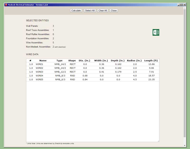
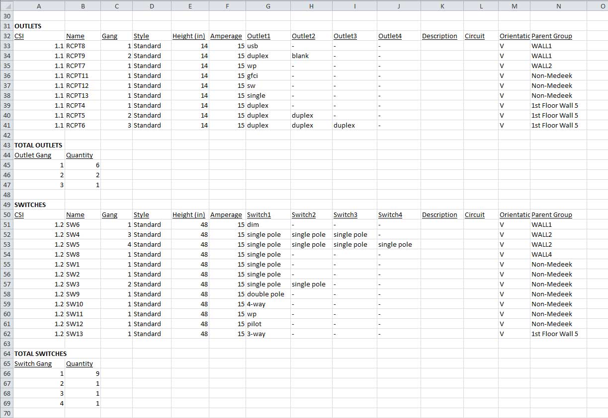
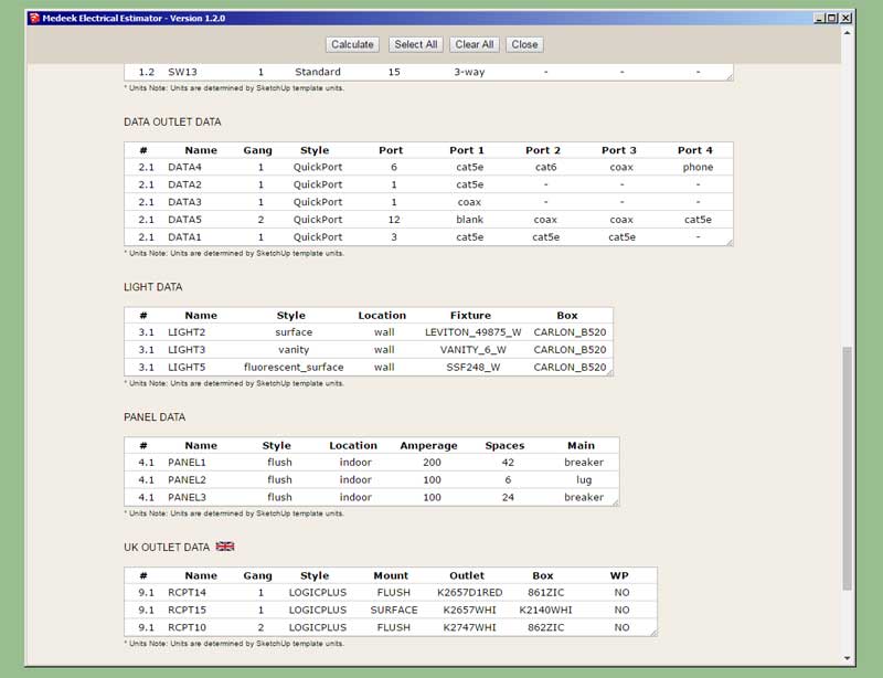
              First look at the CSV output (imported into Excel) for the Electrical Estimator:

              https://aws1.discourse-cdn.com/sketchup/original/3X/6/2/62ac09ba75bec7d9aa486251b2ca3269a996b7e0.jpeg

              *Note, the additional formatting (column spacing, bold, underline) is done in Excel after the import.

              Also note that I have the total lengths tallied for each wire type.

              Nathaniel P. Wilkerson PE
              Medeek Engineering Inc
              design.medeek.com

              1 條回覆 最後回覆 回覆 引用 0
              • medeekM 離線
                medeek
                最後由 編輯

                Version 1.2.3 - 10.20.2020

                • Created the initial framework of the Medeek Electrical Estimating Module.
                • Added wiring to the Medeek Electrical Estimator.
                • Added the ability to export data from the Medeek Electrical Estimator in CSV format.

                http://design.medeek.com/resources/electricalplugin/images/elec_su218_800.jpg

                I also need to figure out what sort of CSI numbering to assign electrical components.

                Nathaniel P. Wilkerson PE
                Medeek Engineering Inc
                design.medeek.com

                1 條回覆 最後回覆 回覆 引用 0
                • medeekM 離線
                  medeek
                  最後由 編輯

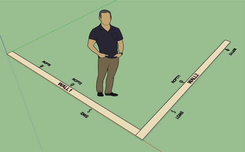
                  In the example shown below I've color coded my network cables based on whether they service the first or second floor of the building. The red cable is the designated switch-to-switch or router-switch cabling:

                  https://aws1.discourse-cdn.com/sketchup/original/3X/6/6/665eedd1292bc34a068a2c095b4261243ddac3f5.jpeg

                  https://aws1.discourse-cdn.com/sketchup/original/3X/e/1/e1d6a067c4519830c179df86c47708efd1f8aa6a.jpeg

                  https://aws1.discourse-cdn.com/sketchup/original/3X/f/8/f840f66df1be4a01487a33993c1e186b6c7df71d.jpeg

                  Note that the totals allows me to determine my cable amounts for each floor. I'm also able to determine that each cable run does not exceed a max. length.

                  View model here:

                  Link Preview Image
                  3D Warehouse

                  3D Warehouse is a website of searchable, pre-made 3D models that works seamlessly with SketchUp.

                  favicon

                  (3dwarehouse.sketchup.com)

                  Once I created all of my cable paths I dropped them onto a separate layer so I could easily hide them (and keep them around for future use if needed) once my wires were created.

                  Nathaniel P. Wilkerson PE
                  Medeek Engineering Inc
                  design.medeek.com

                  1 條回覆 最後回覆 回覆 引用 0
                  • medeekM 離線
                    medeek
                    最後由 編輯

                    Version 1.2.4 - 10.22.2020

                    • Added outlets and switches to the Medeek Electrical Estimator.

                    http://design.medeek.com/resources/electricalplugin/images/elec_su222_800.jpg

                    Nathaniel P. Wilkerson PE
                    Medeek Engineering Inc
                    design.medeek.com

                    1 條回覆 最後回覆 回覆 引用 0
                    • medeekM 離線
                      medeek
                      最後由 編輯

                      First look at UK electrical outlets and switches in the electrical estimator:

                      https://aws1.discourse-cdn.com/sketchup/original/3X/a/c/ac1a2b3b49998e5b3bf7baa1544b17dd9bbe82db.jpeg

                      Nathaniel P. Wilkerson PE
                      Medeek Engineering Inc
                      design.medeek.com

                      1 條回覆 最後回覆 回覆 引用 0
                      • medeekM 離線
                        medeek
                        最後由 編輯

                        Version 1.2.5 - 11.12.2020

                        • Added data (low voltage) outlets, lights, panels, UK outlets, and UK switches to the Medeek Electrical Estimator.

                        http://design.medeek.com/resources/electricalplugin/images/elec_su224_800.jpg

                        The following (six) electrical elements still need to be added into the Electrical Estimator:

                        Safety Devices, Heaters, Vents, Floor Outlets, Low Voltage Panels, Misc. Fixtures

                        Nathaniel P. Wilkerson PE
                        Medeek Engineering Inc
                        design.medeek.com

                        1 條回覆 最後回覆 回覆 引用 0
                        • medeekM 離線
                          medeek
                          最後由 編輯

                          Version 1.2.6- 11.13.2020

                          • Added Safety Devices, Heaters, Vents, Floor Outlets, Low Voltage Panels and Misc. Fixtures to the Medeek Electrical Estimator.

                          The Electrical Estimator is now complete. I still need to change up the CSI numbers for the various components but for now I've just used my own default numbering system. I will need to get with some electrical contractors on what are the appropriate numbers to use.

                          I will now turn my attention to more pressing matters involving the Truss plugin.

                          Nathaniel P. Wilkerson PE
                          Medeek Engineering Inc
                          design.medeek.com

                          1 條回覆 最後回覆 回覆 引用 0
                          • medeekM 離線
                            medeek
                            最後由 編輯

                            Version 1.2.7 - 02.13.2021

                            • Enabled the ability to draw outlets and switches with Medeek Polyline Stemwall assemblies.

                            http://design.medeek.com/resources/foundationplugin/images/foundation_su74_800.jpg

                            Nathaniel P. Wilkerson PE
                            Medeek Engineering Inc
                            design.medeek.com

                            1 條回覆 最後回覆 回覆 引用 0
                            • medeekM 離線
                              medeek
                              最後由 編輯

                              Version 1.2.7b - 02.13.2021

                              • Enabled the ability to draw UK outlets and switches with Medeek Polyline Stemwall assemblies.

                              http://design.medeek.com/resources/foundationplugin/images/foundation_su75_800.jpg

                              Nathaniel P. Wilkerson PE
                              Medeek Engineering Inc
                              design.medeek.com

                              1 條回覆 最後回覆 回覆 引用 0
                              • medeekM 離線
                                medeek
                                最後由 編輯

                                Version 1.2.8 - 04.30.2021

                                • Added optional metadata parameters for UK outlets and switches: description, circuit.
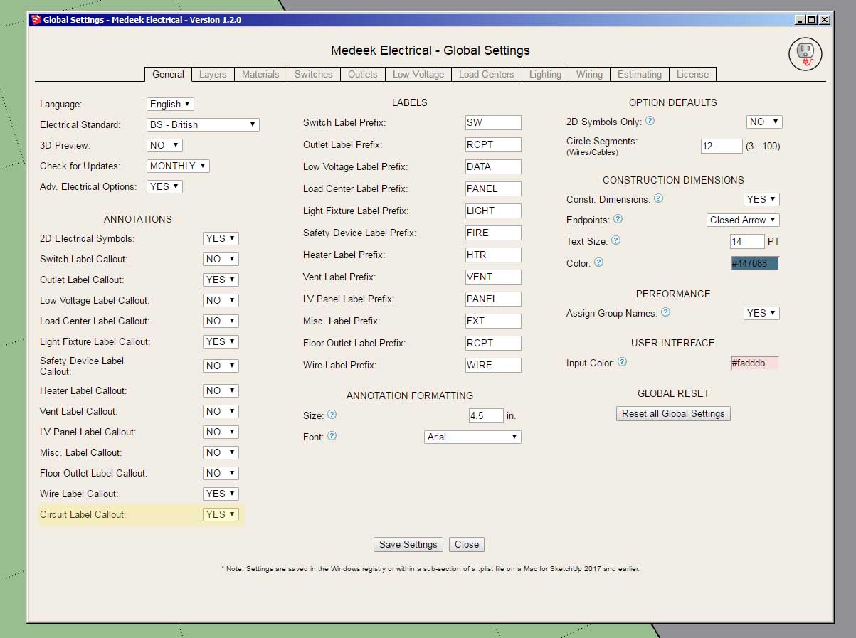
                                • Added a circuit callout parameter in the General tab of the global settings.
                                • Added a 5th dimensioning layer specifically for circuit callouts in the Layers tab of the Global Settings.
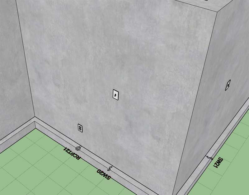
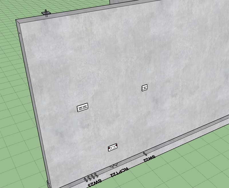
                                • Enabled circuit callouts for the following fixtures: Switches, Outlets, UK Switches and UK Outlets.

                                http://design.medeek.com/resources/electricalplugin/images/elec_su225_800.jpg

                                http://design.medeek.com/resources/electricalplugin/images/elec_su226_800.jpg

                                Nathaniel P. Wilkerson PE
                                Medeek Engineering Inc
                                design.medeek.com

                                1 條回覆 最後回覆 回覆 引用 0
                                • medeekM 離線
                                  medeek
                                  最後由 編輯

                                  Version 1.2.9 - 05.30.2021

                                  • Added an option for vertically offsetting text and symbols within the General tab of the Global Settings.
                                  • Annotation text and symbols for outlets, switches, UK outlets and UK switches can be vertically offset a custom amount from the bottom of the wall.

                                  http://design.medeek.com/resources/electricalplugin/images/elec_su227_800.jpg

                                  http://design.medeek.com/resources/electricalplugin/images/elec_su228_800.jpg

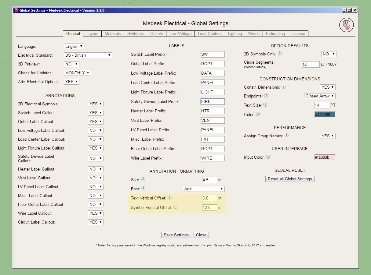
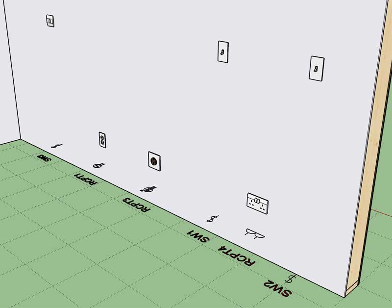
                                  The default placement was at the bottom of the framed wall, and the default offsets still are zero unless otherwise specified differently. However in most situations this resulted in Z-fighting with the subfloor and if a finished floor was modeled then the symbols and text would be buried within the finished floor or carpet (not visible). This option allows the user to customize the vertical placement to suit their particular needs.

                                  This update was per customer request.

                                  Nathaniel P. Wilkerson PE
                                  Medeek Engineering Inc
                                  design.medeek.com

                                  1 條回覆 最後回覆 回覆 引用 0
                                  • medeekM 離線
                                    medeek
                                    最後由 編輯

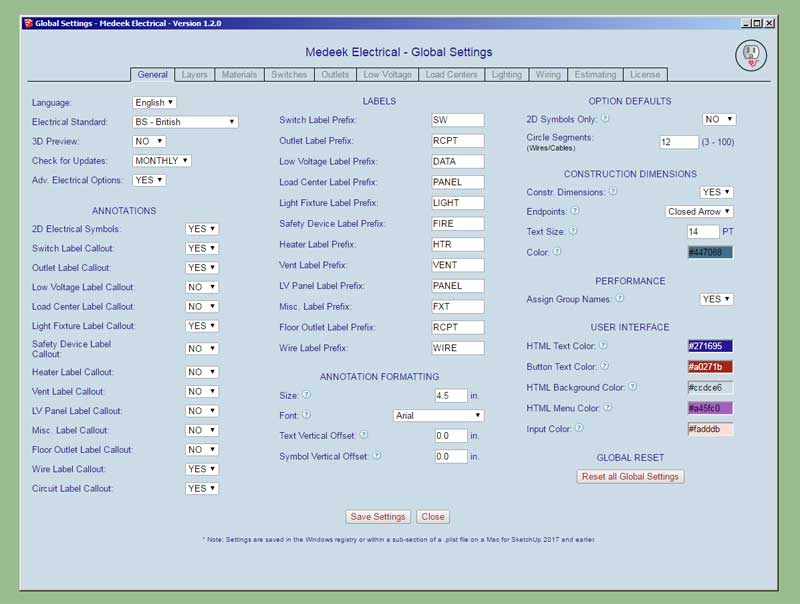
                                    Version 1.3.0 - 06.01.2021

                                    • Added four additional parameters to the "User Interface" section of the General tab of the global settings. This allows the customization (colors) of the HTML menus and buttons.

                                    http://design.medeek.com/resources/electricalplugin/images/elec_su229_800.jpg

                                    Nathaniel P. Wilkerson PE
                                    Medeek Engineering Inc
                                    design.medeek.com

                                    1 條回覆 最後回覆 回覆 引用 0
                                    • medeekM 離線
                                      medeek
                                      最後由 編輯

                                      Version 1.3.1 - 06.16.2021

                                      • Updated the wiring module/algorithm to improve performance and overall robustness.

                                      Nathaniel P. Wilkerson PE
                                      Medeek Engineering Inc
                                      design.medeek.com

                                      1 條回覆 最後回覆 回覆 引用 0
                                      • medeekM 離線
                                        medeek
                                        最後由 編輯

                                        Version 1.3.2 - 07.11.2021

                                        • Enabled subscription and permanent licensing.
                                        • The License tab of the Global Settings now displays the license type.

                                        Nathaniel P. Wilkerson PE
                                        Medeek Engineering Inc
                                        design.medeek.com

                                        1 條回覆 最後回覆 回覆 引用 0
                                        • medeekM 離線
                                          medeek
                                          最後由 編輯

                                          Version 1.3.3 - 01.11.2023

                                          • Enabled layer control integration with the Medeek Project extension.

                                          Nathaniel P. Wilkerson PE
                                          Medeek Engineering Inc
                                          design.medeek.com

                                          1 條回覆 最後回覆 回覆 引用 0
                                          • medeekM 離線
                                            medeek
                                            最後由 編輯

                                            Version 1.3.4 - 06.13.2023

                                            • Enabled switches, outlets and lights to be inserted into "component" walls.

                                            Previously electrical fixtures could only be inserted into walls that were "groups", with this update the wall assemblies can be either groups or components.

                                            This update per customer request.

                                            P.S.
                                            I will still need to update the other misc. electrical fixtures (ie. panels, low voltage, safety, heaters, vents, low voltage panels etc...)

                                            Nathaniel P. Wilkerson PE
                                            Medeek Engineering Inc
                                            design.medeek.com

                                            1 條回覆 最後回覆 回覆 引用 0
                                            • 1
                                            • 2
                                            • 7
                                            • 8
                                            • 9
                                            • 10
                                            • 11
                                            • 9 / 11
                                            • 第一個貼文
                                              最後的貼文
                                            Buy SketchPlus
                                            Buy SUbD
                                            Buy WrapR
                                            Buy eBook
                                            Buy Modelur
                                            Buy Vertex Tools
                                            Buy SketchCuisine
                                            Buy FormFonts

                                            Advertisement