FlexTools Updates
-
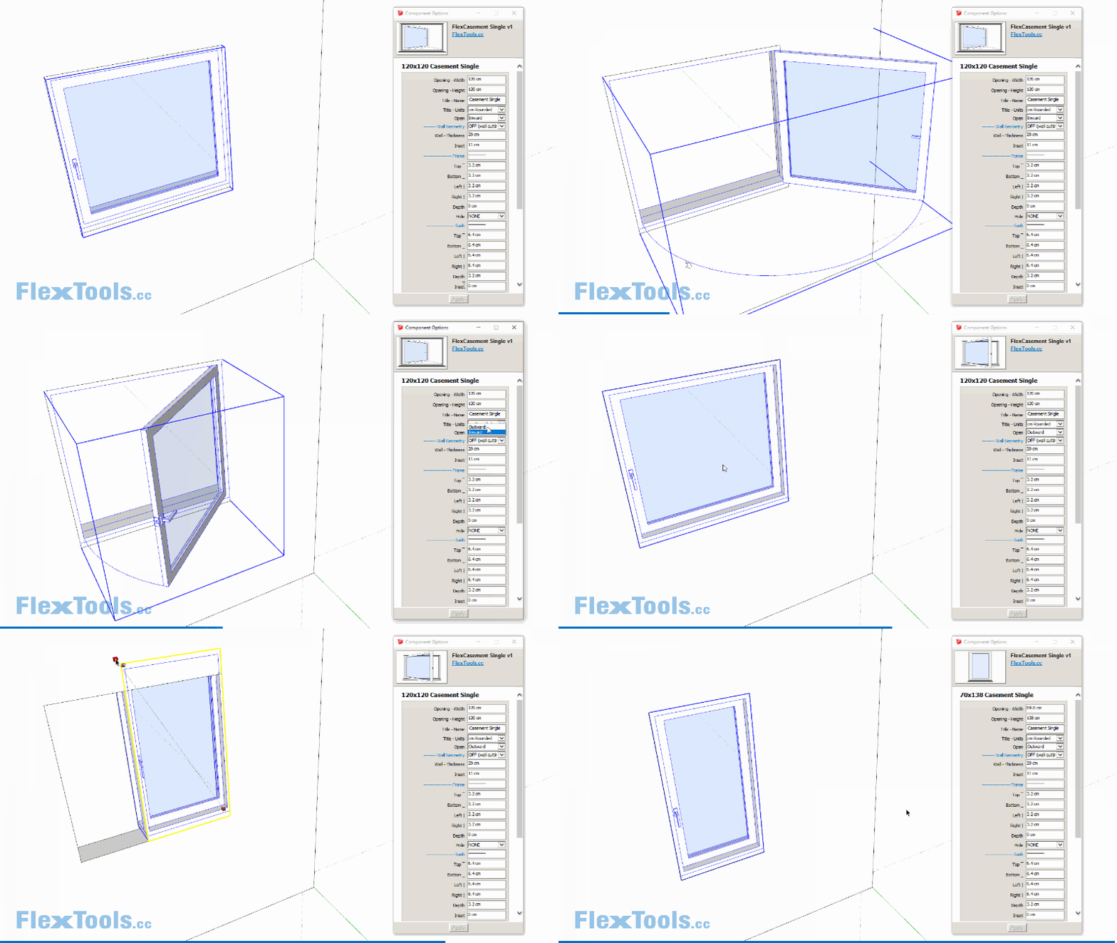
Casement-Single Flex Window
It’s just like the recently released Casement-Double, but single!

-
Looks great. Are you sure about the handle placement for hoppers and awnings? Can the handle be omitted?
-
@pbacot said:
Looks great. Are you sure about the handle placement for hoppers and awnings? Can the handle be omitted?
Hi pbacot,
The handle in the hoppers and awnings (and in the casements too) are placed by default like in a tilt and turn window, but they aren't tilt AND turns, rather just tilt, OR Turn... So you have a good point!

I'll add an option to center the handle on the lower rail for it to suit tilt OR turn windows!
The handle's placement, visibility and rotation can be easily changed. Double click into the component and select it:
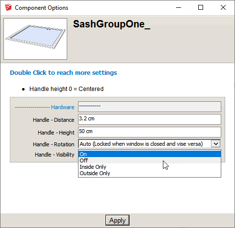
You can choose to hide it completely.
You can have it visible on one side of the window or the other.
(It may sound weird to have the handle on the outside, but it makes sense when you start flipping the window in and out and if you happen to like placing windows from the interior rather than from the exterior, or if you'd like to use the casement windows as doors...)You can also delete the handle all together if it bothers you - no harm will be done, everything else will continue working.
You can also swap the handle with others or customize the handle manually to any handle you choose following the instructions here: https://flextools.cc/learn/flexdoor/hardware/
It may look daunting, but once you get the hang of it, making your own dynamic handle is a matter of minutes.I hope that all makes sense.
-
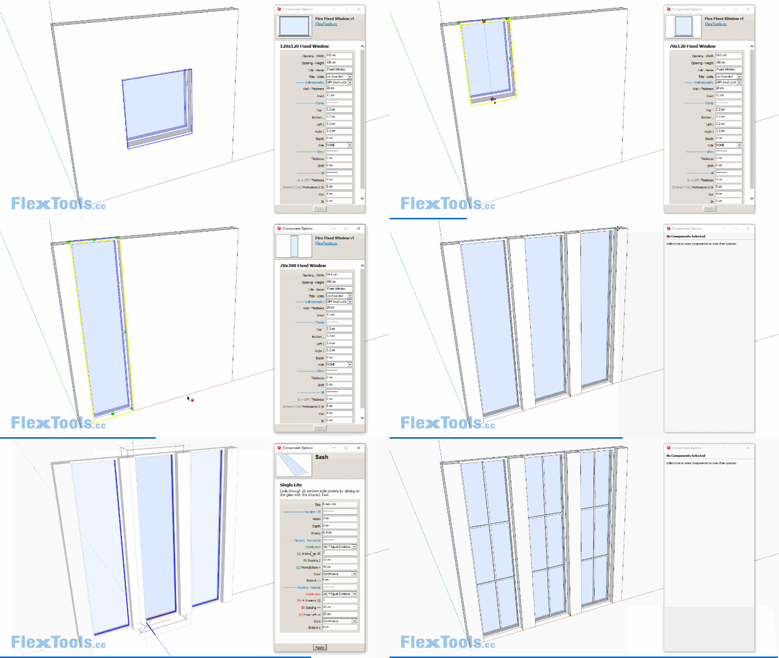
A Fixed Flex Window
It's similar to the original FlexWindow, but it is a lot simpler.
Read more details in the FlexBlog: https://flextools.cc/blog/3-new-flex-windows/
-
We started working on FlexStairs!
Here is a work-in-progress video:
- The stairs are recalculated while scaling according to the restrictions you enter (based on Blondel's Rule).
- The top step can be hidden.
- You can set a minimum riser height.
- You can also set a fixed tread length.
To be continued...

-
Personally I’d say that if the tool does the various possibilities structurally it should be fine as longs as components are used. The range of possibilities for balustrades and handrails together with inlays, finishes, nosings, etc. is so wide that I’d rather take the time to customize the components particular to the application than try to fiddle with numerous settings to see what it comes out like only to end up doing a partial custom job anyway. Remember to work in landings and being able to set governing parameters for that.
-
Where can I find wooden double doors like in gif?

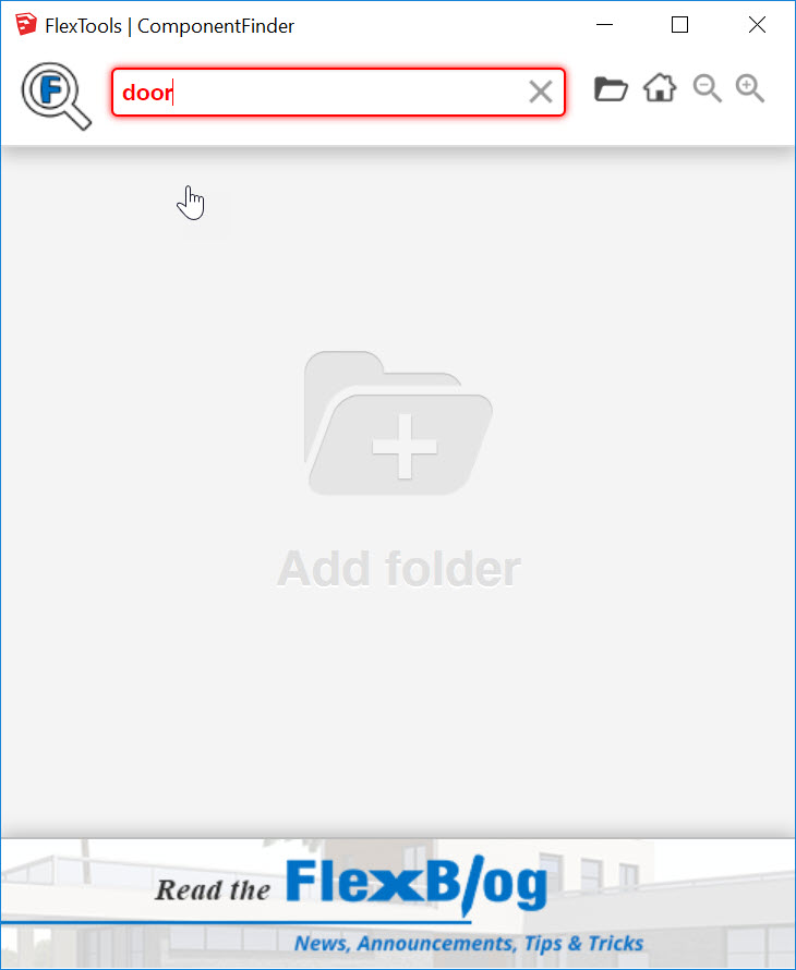
Also in my(Activated)ComponentFinder text is red when searching and doesn´t work.?
-
@epix3d said:
Where can I find wooden double doors like in gif?
Hi Epix,
The components in that animation were all components I created with the Flex components as a base.
-
Pull in a FlexDoor component.
-
Change the door to a double door in the component options window - double click into the component and then select it to reach the correct options window and change number of doors to 2.
-
Change the handles with handles from the 3DWarehouse and then recalibrate their location with the interact tool.
-
Add which ever wood material to the sub-components you want.
- You can then save the component with component finder for later use:
@epix3d said:
Also in my(Activated)ComponentFinder text is red when searching and doesn´t work.?
The red text appears if nothing comes up when searching. Since it appears you have no folders open it won't find anything for sure. Add a few folders and then search through them and it should work as expected.
Please let me know how it works out.
-
-
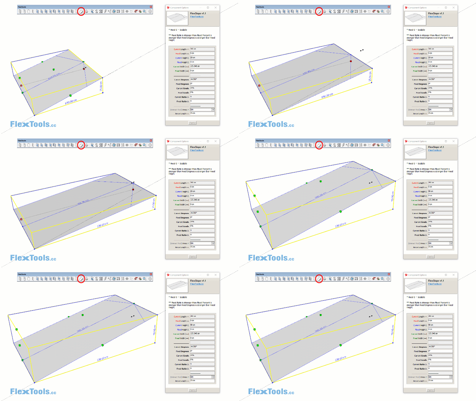
FlexSlope
New FlexSlope Component easily calculates ramps, car parks, roofs etc.
The original, simpler beta version is available for free download at the FlexLabs.See more details at the FlexBlog.
-
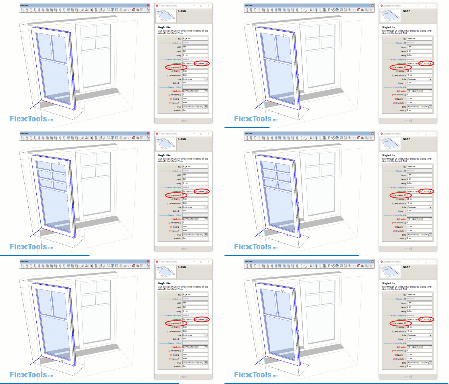
You can now also specify the number of divisions in Colonial Style Distributions.
More updates in our Blog: https://flextools.cc/blog
-
@halroach said:

You can now also specify the number of divisions in Colonial Style Distributions.
More updates in our Blog: https://flextools.cc/blog
I tried once last night and twice today, this update is not installing via the FlexTools Manager. It keeps on showing the update is available, even after restarting SU and after restarting the machine.
-
@juju said:
I tried once last night and twice today, this update is not installing via the FlexTools Manager. It keeps on showing the update is available, even after restarting SU and after restarting the machine.
Hi Juju,
-
Hmmm, what happens when you update? Does it show it downloading and installing or nothing happens?
-
Are you getting any error messages?
-
Anything in the console? Window > Ruby Console
-
Please send any log files you find to yoni@flextools.cc:
C:\ProgramData\F3d_FlexTools\logs
I'm available on the flextools.cc chat now if you have the time and we'll figure out what's going on.
-
-
I've sent an e-mail to the address provided in the post above.
-
@juju said:
I've sent an e-mail to the address provided in the post above.
Got it! we're looking into it.
-
-
Problem solved, thanks for the rapid feedback on a solution!
-
FlexStairs released!


We’re proud to present you with FlexStairs v1 - the fastest stairs ever!
Scale the stairs from floor to floor and they automatically adjust according to your requirements.
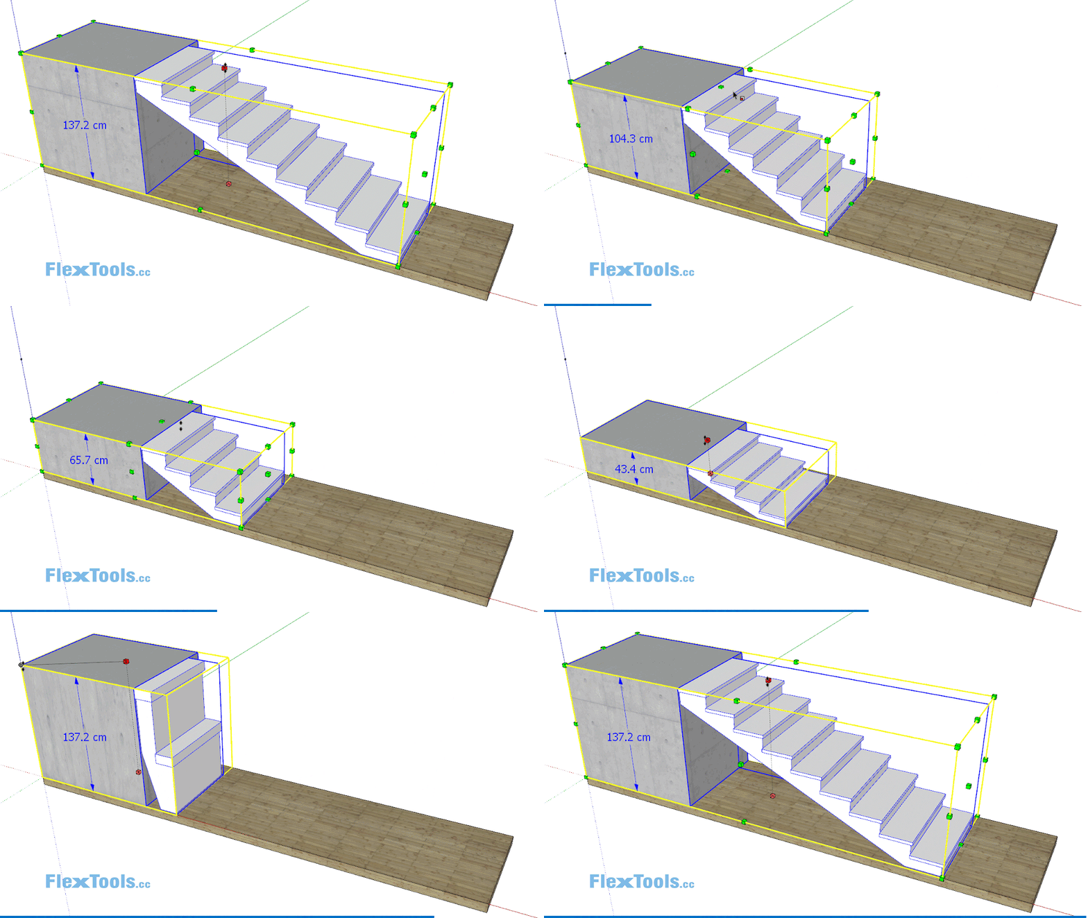
Learn more at the FlexBlog
-
That looks awesome!
-
Have to figure out some steps? - No worries.
FlexStairs will do the math for you!
See how FlexStairs work in this short introduction video:
Learn more at https://flextools.cc/learn/flexstairs
-
Advertisement


