Medeek Wall Plugin
-
maybe collapse the wall sheathing section as well so it's only opened if you need to edit it.
-
Version 3.3.6 - 11.18.2023
- Added a "Menu UI" parameter in the General tab of the Global Settings with the following options: Legacy, Collapsed, Expanded.
- Updated the Wall Draw and Edit menus with the new Menu UI options.
- Fixed a bug with the tee intersection algorithm for rectangular "stacked" walls.
The additional menu options are in response to feedback from multiple users requesting a less busy and simpler menu system. By default the legacy menu system is selected in the global settings however one can quickly change to one of more advanced "collapsible" systems. This is my first real crack at this so further refinement may be necessary depending on the feedback I receive.
-
Tutorial 45 - Menu UI Options (8:08 min.)
-
Version 3.3.7 - 11.20.2023
- Fixed a bug with the hotkey (Up key) for wall panelization in the Draw Wall Perimeter tool.
- Fixed a bug with the Draw Wall Perimeter tool for metric units.
!!!! Critical Bug Fix !!!!
This is a critical bug fix for users of metric units. I highly recommend upgrading to this latest version for all users. -
Version 1.3.8 - 11.22.2023
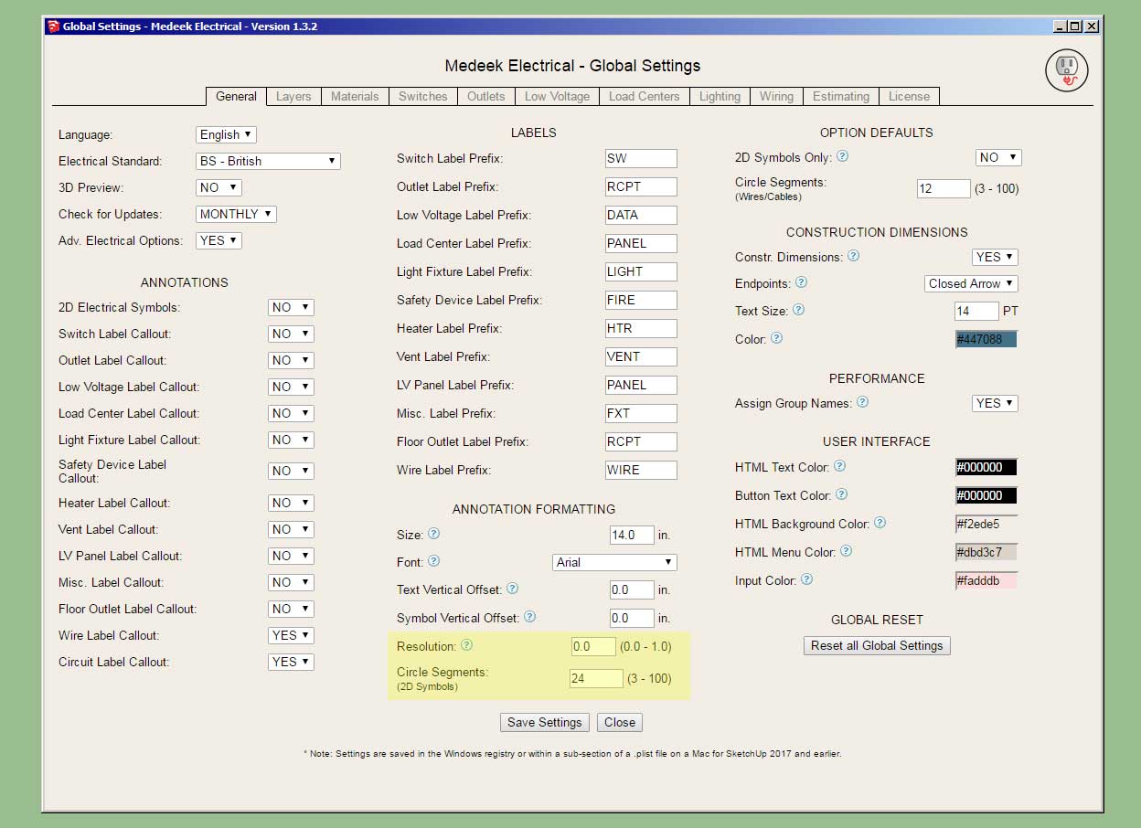
- Added two additional parameters for annotation formatting.
- Added the "Regen Electrical" function to the primary toolbar, enabled regeneration for all electrical fixtures.
- Moved the "Draw Safety Device" tool to the secondary toolbar.


-
Version 3.3.7b - 11.27.203
- Fixed a critical bug introduced with Version 3.3.6.
!!!! CRITICAL BUG FIX !!!!
This is a critical bug fix for all users, please download the latest version of the plugin (3.3.7b). -
Version 3.3.8 - 12.02.2023
- Updated the face selection algorithm of the draw wall perimeter tool.
This addresses the issue of selecting faces that are embedded or nested within groups. You can now select faces that are in the root of the model or nested within other groups.
-
Version 3.3.9 - 12.18.2023
- Added a "Cedar Siding" built-in material (horizontal) into the material library.
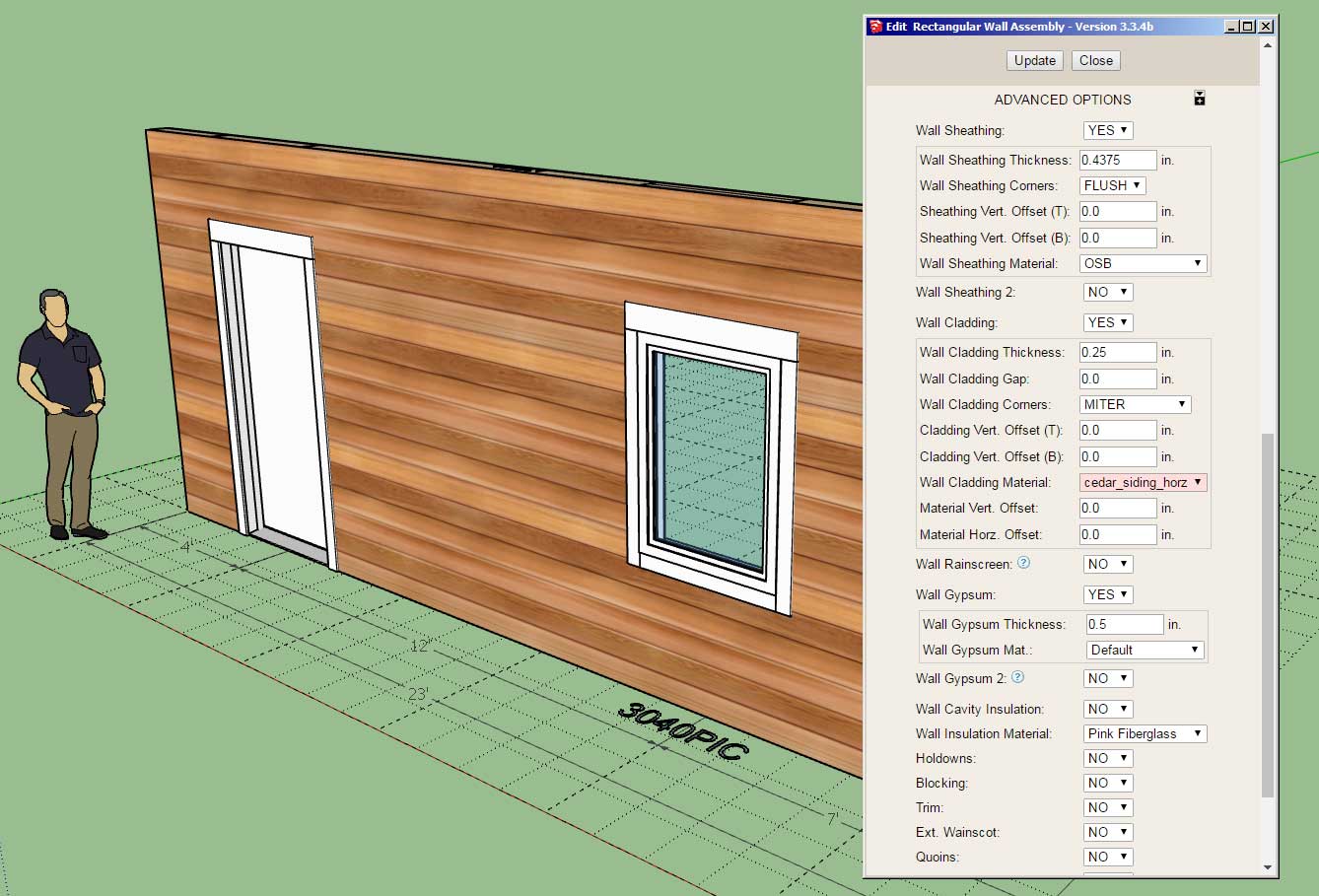
This material is a horizontal version of the previously added vertial version. This update per customer request.
-
Version 3.4.0 - 12.22.2023
- Fixed a minor bug with the error checking code for custom casing profiles of windows and doors.
- Added top and bottom vertical offset parameters for shearwall sheathing.
- Added a QHQ casement window to the window draw and edit modules.
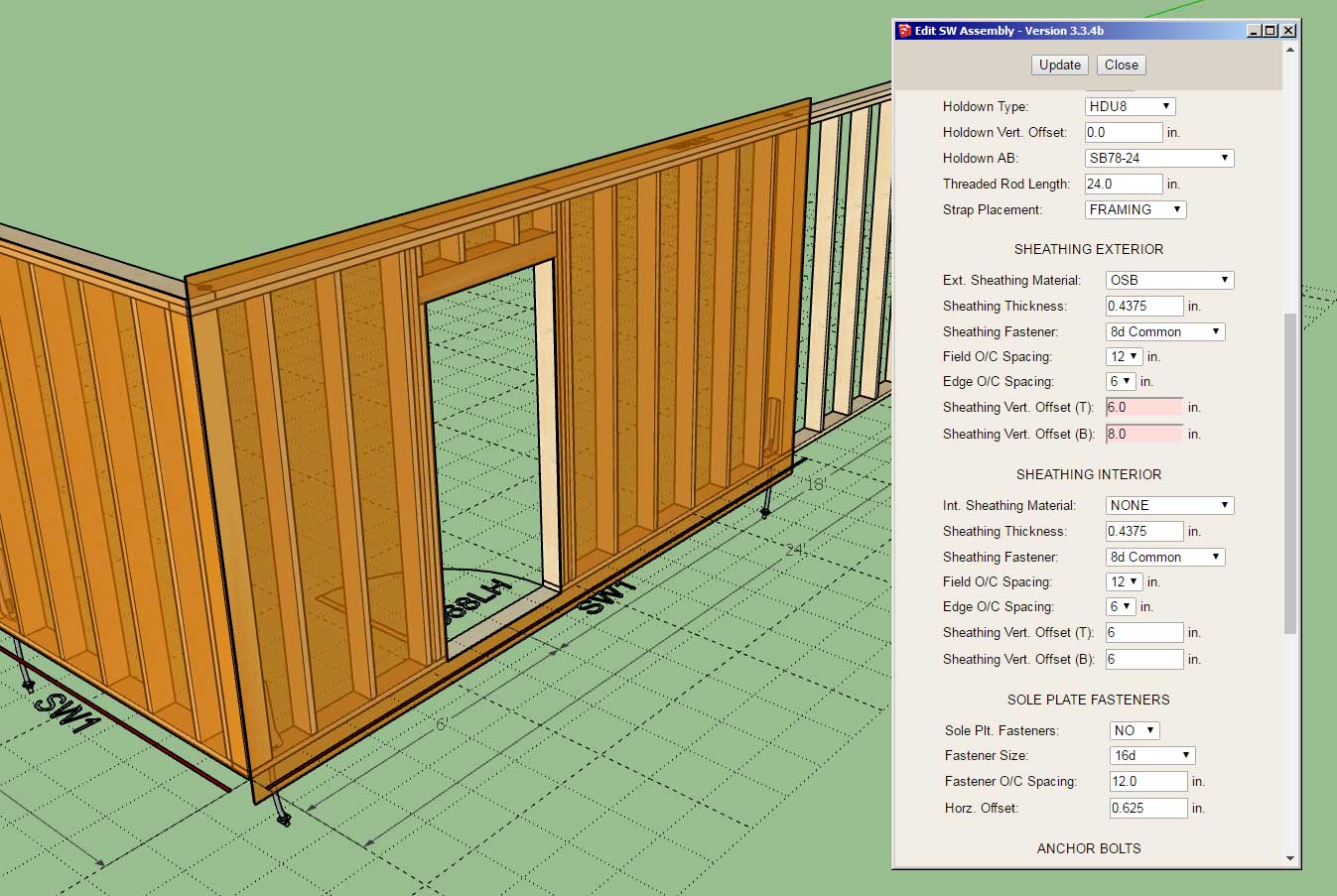
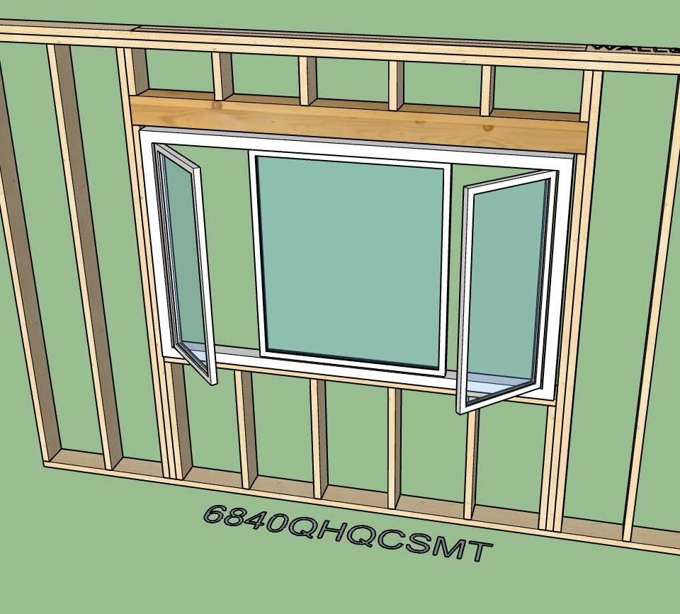
Both updates are per customer request.
-
Version 3.4.1 - 12.29.2023
- Updated and improved the license verification module.
- Disabled redundant logging to improve plugin performance.
-
Version 3.4.2 - 01.09.2024
- Fixed a bug with steel framing and tee intersections.
- Fixed a bug with hip walls and tee intersections (two stud with blocking).
-
Version 3.4.3 - 01.18.2024
- Improved the serial number verification logic within the License tab of the Global Settings.
- Added a Door Reset button in the Doors tab of the Global Settings.
- Added a Window Reset button in the Windows tab of the Global Settings.
-
Version 3.4.4 - 01.24.2024
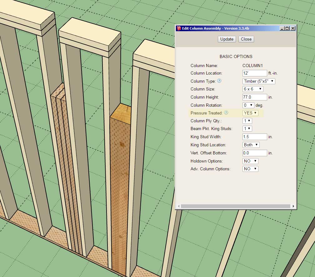
- Added a pressure treated option for in-wall columns.
- Created a more realistic material/texture for pressure treated timbers (for in-wall columns and posts).
-
one thing i recently ran into was needed a steel column to support a steel beam spanning a couple of walls to get the proper support for ceiling joists. it would be a nice option (not necessarily to provide a steel column in leiu of a wood one
 ) but just to leave the space for easily adding one separately (and thus avoiding closing it etc when regenerating due to a wall change).
cheers!
-
I could provide another option in the Advanced Options section which essentially removes the column and leaves a blank opening in wall. Is this what you are suggesting?
-
yes, or even just have a column type of "blank" (or simply marker) in the selection list (along with x dia round steel, x by x wood, etc)
 this way the code is effectively the same, just whether or not the spacing has anything other than say a 2D marker of the column location.
 -
Version 3.4.5 - 01.28.2024
- Added two additional column types for in-wall columns: Custom, Blank.
- Three additional parameters added for custom in-wall columns.
- Added a custom label option and annotation section for in-wall columns.
- Updated the javascript logic within the License tab of the Global Settings.
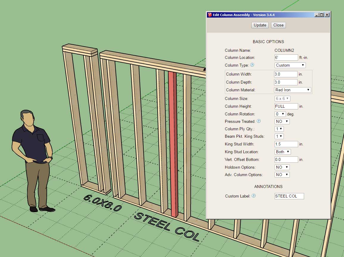
Technically this update is a bit redundant because one can already configure custom in-wall columns within the global settings. However, this new option gives one the ability to insert any sort of column into the wall (non-wood) as well as a blank opening where one could then insert their own manually modeled column or structural support.
The custom label option applies to all column types, so it can override the auto labeling algorithm of the module.
This update per customer request.
-
thanks! this will be handy as i design a lot of studio where the isolation structure has to be separated from the exterior and custom columns and sizing it for that critical 2" separation, using i-beams and glulams, when using autogenerated walls etc will make this much easier to draw and document

-
Version 3.4.5b - 01.28.2024
- Fixed a bug with holdowns for in-wall columns.
- Fixed a bug with the bottom plate cutting algorithm for in-wall columns.
-
Version 3.4.6 - 01.30.2024
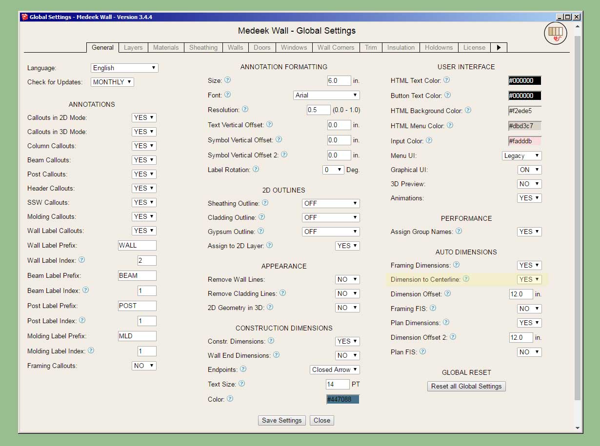
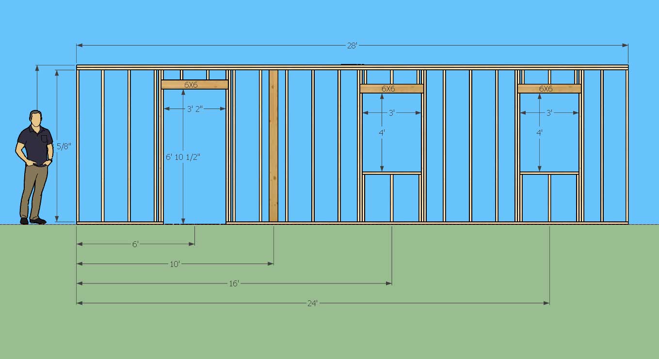
- Added a "Dimension to Centerline" option for framing dimensions in the General tab of the Global Settings.
- Enabled centerline dimensioning for openings, columns and SSW for rectangular walls.
- Added a "Style 5" (Pull Plate) to the built-in door hardware options.
- Added more options for grid style window grilles: 3X4, 4X5, 5X6.
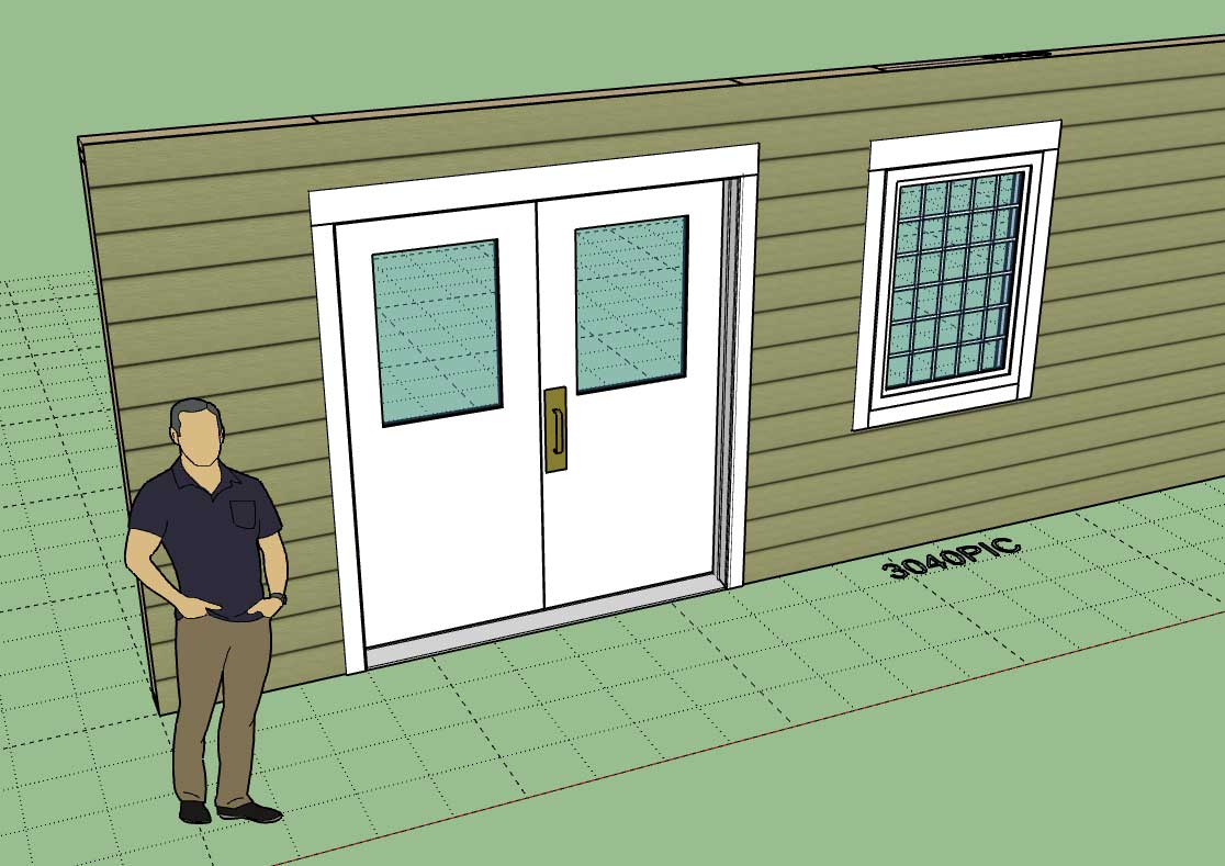
All updates per customer requests.
Advertisement


