Foundation Plugin
-
Version 1.0.0 - 07.03.2016
- Created Medeek Foundation Plugin, utilizing SketchUp's Ruby API.
- Added slab on grade foundation type (rectangular outline only).
- Added garage curb and interior footing options.
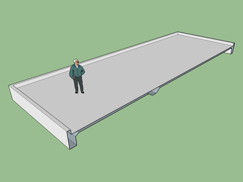
View model here:
3D Warehouse
3D Warehouse is a website of searchable, pre-made 3D models that works seamlessly with SketchUp.
(3dwarehouse.sketchup.com)
The thing that would make this plugin particularly useful is if the user could define a polygon outline for the foundation, that will be next, then onto stemwall foundations.
-
Link to the plugin web page (under construction):
The toolbar icons:

-
My wife kindly pointed out that the interior footing might not extend the full width or length of the building, very good point. To correctly specify an interior footing you also need a start and end point, so five inputs total to define this feature:
Direction: X Dir or Y Dir
Footing Width:
Footing Depth:
Start: Measured from first selection point that defines foundation outline.
End: Measured from first selection point that defines foundation outline, must be greater than Start length.An example of a partial width interior footing:
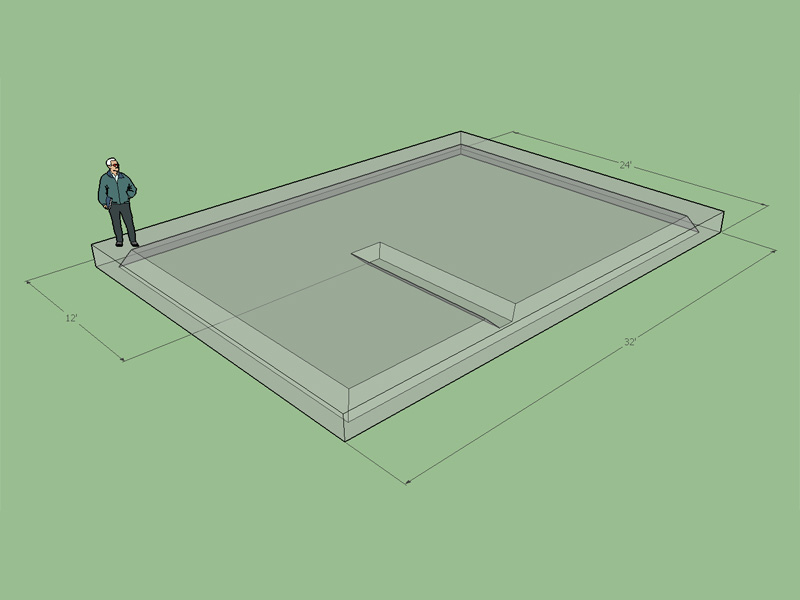
View model here:
3D Warehouse
3D Warehouse is a website of searchable, pre-made 3D models that works seamlessly with SketchUp.
(3dwarehouse.sketchup.com)
The problem with the basic UI is that it only allows for one interior footing. If I webdialog this input menu I can show the layout of the foundation in plan view and allow for an unlimited number of interior footings as well as have footings running in both the X and Y direction. The possibilities are really endless.
The same methodology would apply for an arbitrary polygon shaped foundation.
-
Interior footings are so variable. You might not have these all figured out long after the others, because they are only needed in certain structural requirements, which are figured out later in the process. Then there are pads for posts.
This looks like a great start! Foundations can become very complex, but getting the basic perimeter in would be nice, especially where it can be pushed and pulled for modifications later--letting you have a simple base for your preliminary model. When I think of my projects it's seems each one has one special condition after another.
-
The ability to go back in and easily edit a foundation without having to recreate it will be crucial to the success of this plugin.
Version 1.0.1 - 07.05.2016
- Enabled partial width interior footings for slab on grade foundation.
- Addressed minor bugs with UI geometry menu: Interior footing depth can now be specified.
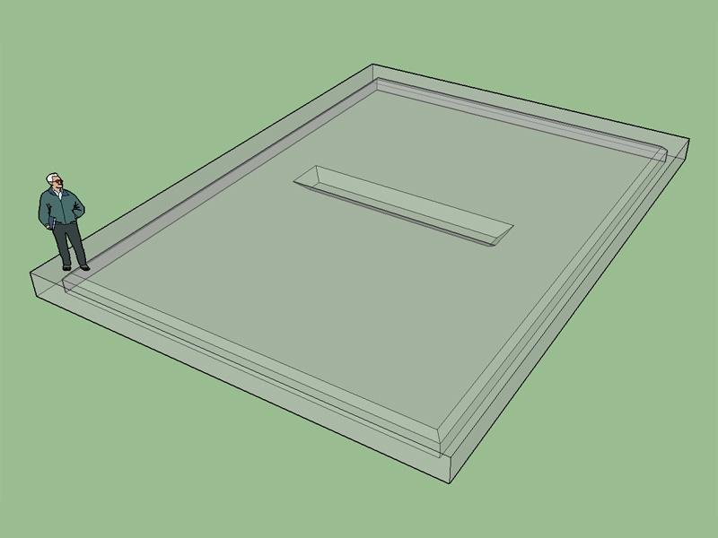
View model here:
3D Warehouse
3D Warehouse is a website of searchable, pre-made 3D models that works seamlessly with SketchUp.
(3dwarehouse.sketchup.com)
Interior footings quickly complicate things but a well designed html UI should clarify things greatly and make it much more intuitive. That will be the next objective.
-
how about the ability to exclude area (-s), eg. island areas?
if I were to be interested by this I would probably only use it for slabs without plinth walls (have Profile Builder 2 for this), etc. - thus ability to add sub-base layers and specify thicknesses would help.
EDIT:
Also the ability to add specified layers on top of the slab would help automate 3D modeling.
Then to be able to specify the TOC or FFL as origin from which to build the configuration would be great!
-
Currently the top of the slab is the origin. What do you mean by layers on top of the slab?
-
Certainly, juju, I'd assumed that a Medeek plugin would be moving towards all sorts of options: plinth wall, no plinth wall, raised floor,retaining wall, basement, garage (floating) slab...
-
If the exclusion area is simply a hole in the slab then it is probably easiest just to push/pull a hole in the slab. However, if the exclusion area is a large opening with footings required at the perimeter then that is a different matter. It might look something like this:
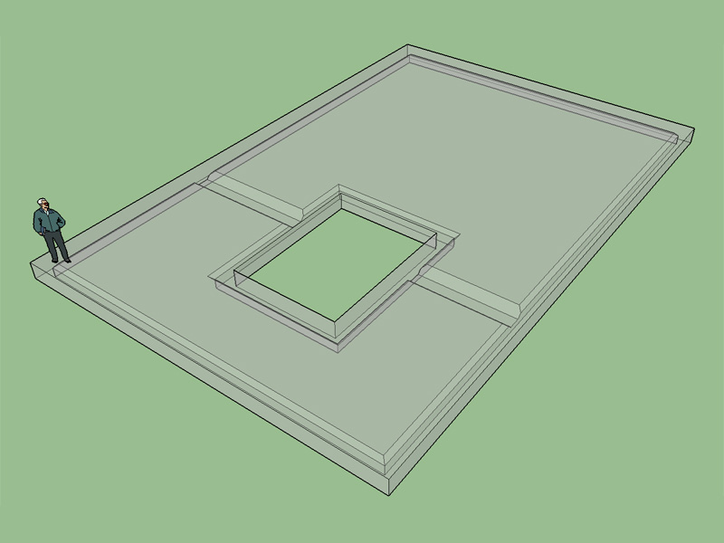
View model here:
3D Warehouse
3D Warehouse is a website of searchable, pre-made 3D models that works seamlessly with SketchUp.
(3dwarehouse.sketchup.com)
Note how the opening bisects the interior footing, which does potentially complicate any algorithm that would generate the hole and perimeter footing. I will have to give this some more thought...
-
Typical stem wall foundation (crawlspace) with interior strip footing and floor beam. This is what is built locally around these parts (Ocean Shores, Washington):
View model here:
3D Warehouse
3D Warehouse is a website of searchable, pre-made 3D models that works seamlessly with SketchUp.
(3dwarehouse.sketchup.com)
-
Nice.
If the girder is only supporting the floor, around here we use isolated post and piers without the connecting footing.
-
I've seen the footings done both ways. Locally the majority of homes are built very close to the beach directly on sand with a high water table that fluctuates with the tides. The strip footing helps prevent shifting of the piers and posts and uneven settlement.
Out of curiosity what are the typical dimensions of your piers? and posts?
Some contractors locally like to use 4x4 posts and some default to 4x6 with a floor beam size of 4X8 fairly typical. When I do the engineering I will check the floor beams and posts as well as the soil pressure at the footing but I rarely encounter a problem.
-
Version 1.0.2 - 07.08.2016
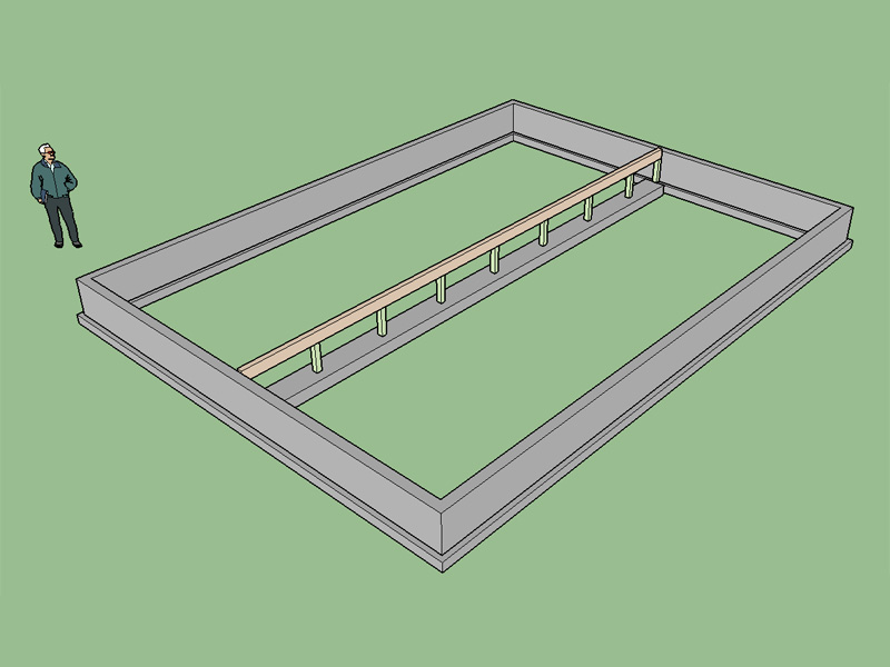
- Added stemwall foundation type (rectangular outline only).
- Enabled post and pier interior floor beam(s) with a strip footing.
- Added brick ledge option to stemwall foundation.
View model here:
3D Warehouse
3D Warehouse is a website of searchable, pre-made 3D models that works seamlessly with SketchUp.
(3dwarehouse.sketchup.com)
The interior floor/footing assembly is grouped as a component so that adding extra floor beams or moving them is easily accomplished.
-
Something that will working with every start surface will be very fine!

(Flying Forewoman!
-
Would it be easier for a user to pick a number of points to describe a polygon or to have a tool that allows one to select an existing face as that polygon? I also need a stemwall tool that allows one to create single walls (curved or linear) since there are times where you do not want to create a closed polygon outline.
-
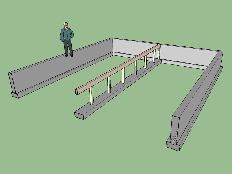
When the user selects a type B footing (stemwall foundation) a keyway is inserted between the stemwall and footing:
View model here:
3D Warehouse
3D Warehouse is a website of searchable, pre-made 3D models that works seamlessly with SketchUp.
(3dwarehouse.sketchup.com)
-
View Medeek skp models in 3D Viewer
When viewing plugin at given link such as
https://3dwarehouse.sketchup.com/model.XXXXXX
you can activate the 3D WebGL Viewer to inspect the 3D Model.

-
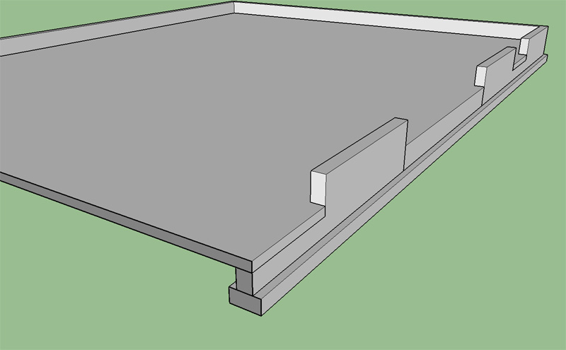
I'm trying to determine which is the preferred method of blocking out a stemwall foundation for garage doors where a slab will be poured in the garage. I've seen it done both ways. Option 1 does not typically block all of the stemwall out and seems to be more common in locations where the frostline is deeper (24" or deeper). Option 2 completely blocks out the stemwall at the garage door and then a thicken edge is poured where the slab meets the footing at the garage door. From a structural point of view which is the better method and also from a construction point of view what are the pros and cons?
Option 1:
Option 2:
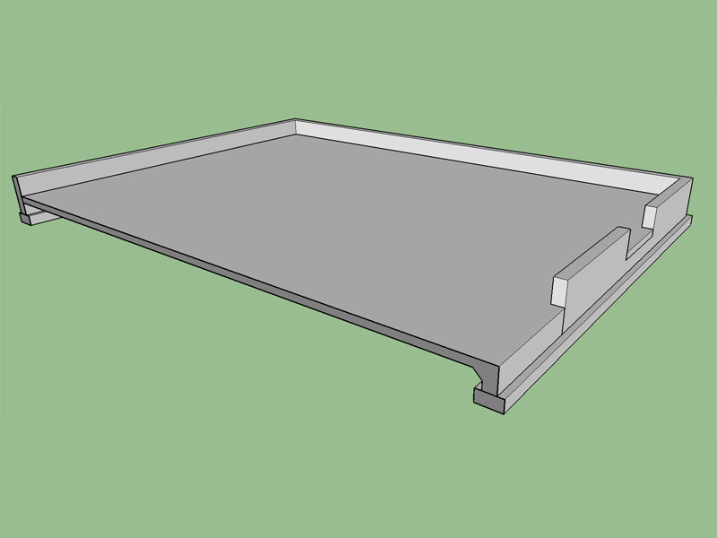
View model here:
3D Warehouse
3D Warehouse is a website of searchable, pre-made 3D models that works seamlessly with SketchUp.
(3dwarehouse.sketchup.com)
-
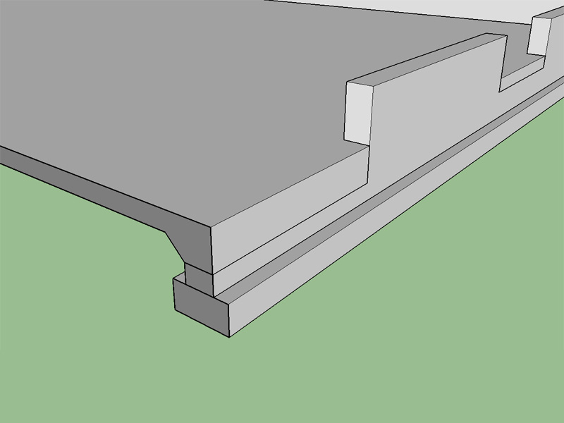
I should point out I've also seen a sort of a combination of the two options where the blockout does not extend to the footing but a thickened edge is employed at the slab/door interface and the thickened edge is typically 2x the slab thickness, or called out as a minimum dimension of 8".
Option 3:
-
That looks like a better one. Then there's someone I am working with now who wants the slab floating and not resting or tied to the foundation at all. Preference could depend on soils.
Advertisement


