Split Face Problem
-
Tried, but cannot figure out how to get the 'split' out of the face(s)... I would like to see it as one face... like all the others...
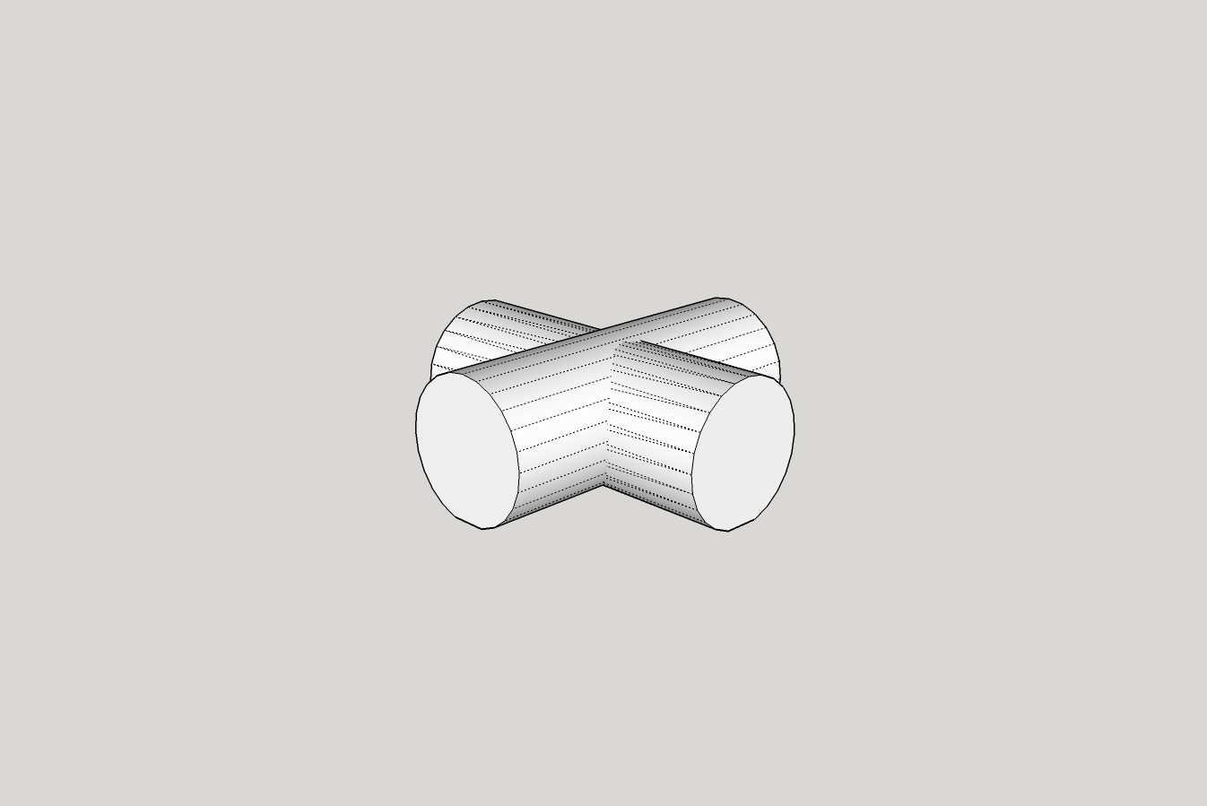
90 deg-Core.skp -
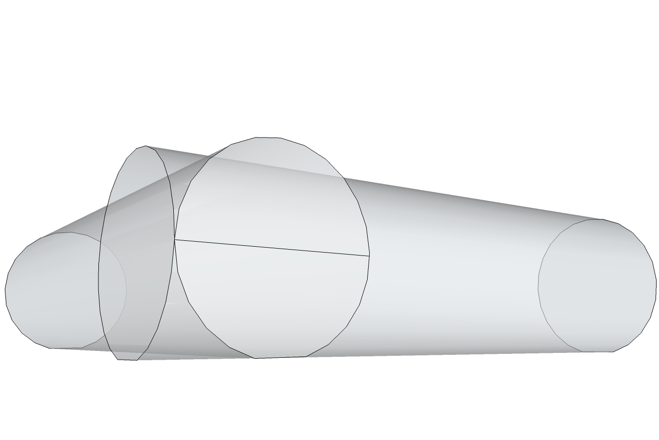
The cylinders are touching so there is an edge there.
If you turn on hidden geometry you can see it on the other face.
Use ctrl with the eraser to soften the edge.
-
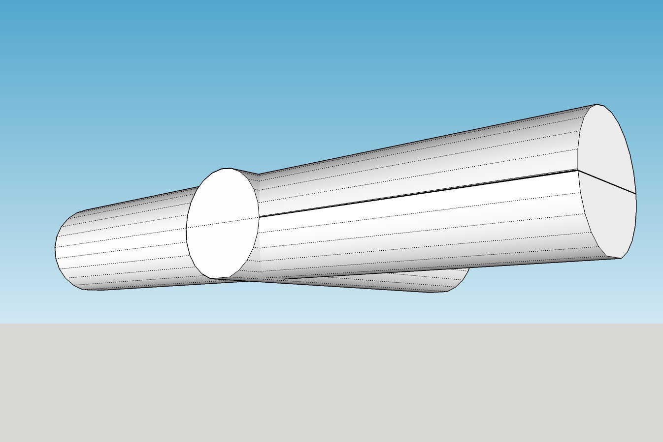
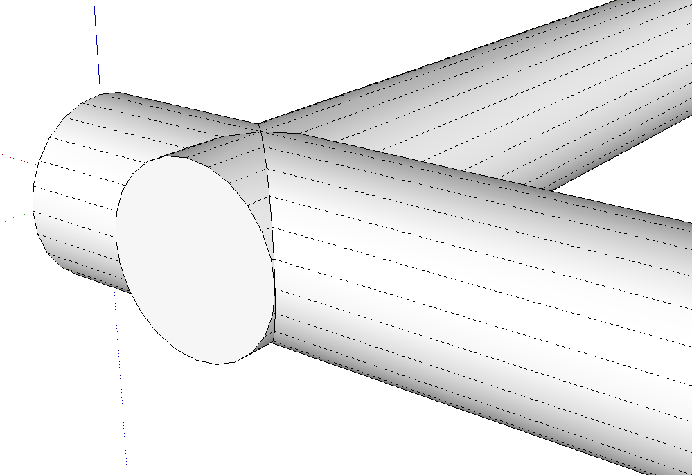
Thank you, good tip... but I still have the problem that the face is still split...
If I enter the edit mode for the group, select the Push/Pull Tool, only half the circle is selected for, in my case, trying to pull the face to make it longer... I have to pull each half... when I tried that the halves were not 'joined' , so the model ended up with an open face and can't be printed. I would have to manually try to close the face...
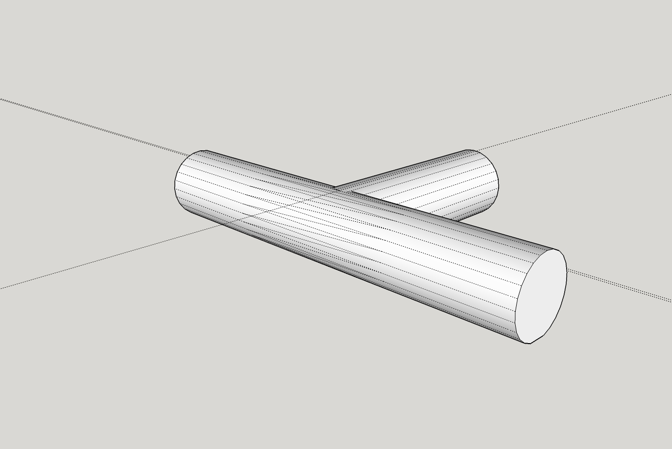
Tee-Core.skp
PS, like your animation... how did you do that? -
@moot said:
Thank you, good tip... but I still have the problem that the face is still split...
If I enter the edit mode for the group, select the Push/Pull Tool, only half the circle is selected for, in my case, trying to pull the face to make it longer... I have to pull each half... when I tried that the halves were not 'joined' , so the model ended up with an open face and can't be printed. I would have to manually try to close the face...
[attachment=1:ygmbntds]<!-- ia1 -->Tee-Core.jpg<!-- ia1 -->[/attachment:ygmbntds]
[attachment=0:ygmbntds]<!-- ia0 -->Tee-Core.skp<!-- ia0 -->[/attachment:ygmbntds]
PS, like your animation... how did you do that?Unless you intersect the two cylinders, the edge needs to be there. It is part of the round surface. Turn on X-Ray to see the other edges.
-
When I saved the 90 deg-Core.skp SU gave me the option to fix problems... I did.
When I load the 90 deg-Core.stl into the printer software (Dremel3D Idea Builder) I do not get any error(s) or warning(s) about open faces and the model prints fine.
When I pull the face(s) (as shown in Tee-Core.jpg) I end up with the 'open face(s) in model' issue.
@wo3dan said:
...Unless you intersect the two cylinders, the edge needs to be there. It is part of the round surface. Turn on X-Ray to see the other edges.
I added two lines (where to halves were split) and then did a select all, selected Intersect, With Model... When I tried to load model, I got the 'open face(s)' error...
So, any hints on what I'm doing wrong?
-
If you want to avoid the end of the cylinder being split by the edge on the side of the other, you'll have to extrude the cylinder slightly farther. Edge spliting the end of the cylinder is an edge on the other other cylinder that is tangent to the face. Of course the edge will split the face.
Extend the cylinder beyond and it won't split the face.
If you need the thing to be solid for 3D Printing, you'll need to intersect the cylinders and then remove internal faces. If you do that, you can then push the end of the cylinder back to the other cylinder and avoid the split face. That's because there'll be no edge to split the face.
-
Thanks again, you make it look easy

I did searches on rove internal faces but looks like plugin?
Can you recommend one? -
There are plugins to do that but it's certainly not difficult to do it with native tools. After intersecting the cylinders, I just hid an end of a cylinder and deleted the internal faces by selecting them and hitting Delete. I would suggest you learn to do it that way before you start looking for an extension to do it.
-
Will do, thanks...
-
Rove is a typo. Dave meant to say Remove internal faces.
-
@dave r said:
There are plugins to do that but it's certainly not difficult to do it with native tools. After intersecting the cylinders, I just hide an end of a cylinder and delete the internal faces by selecting them and hitting Delete. I would suggest you learn to do it that way before you start looking for an extension to do it.
I was trying... I wrestled with the 'intersecting'... got frustrated... what I ended up doing was starting over (as suggested in other posts)...
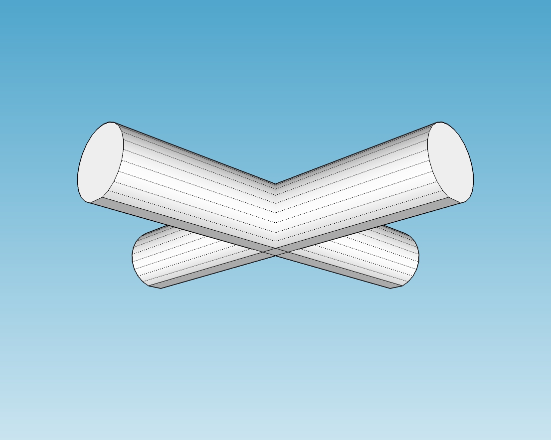
I took my original Strt-Core,
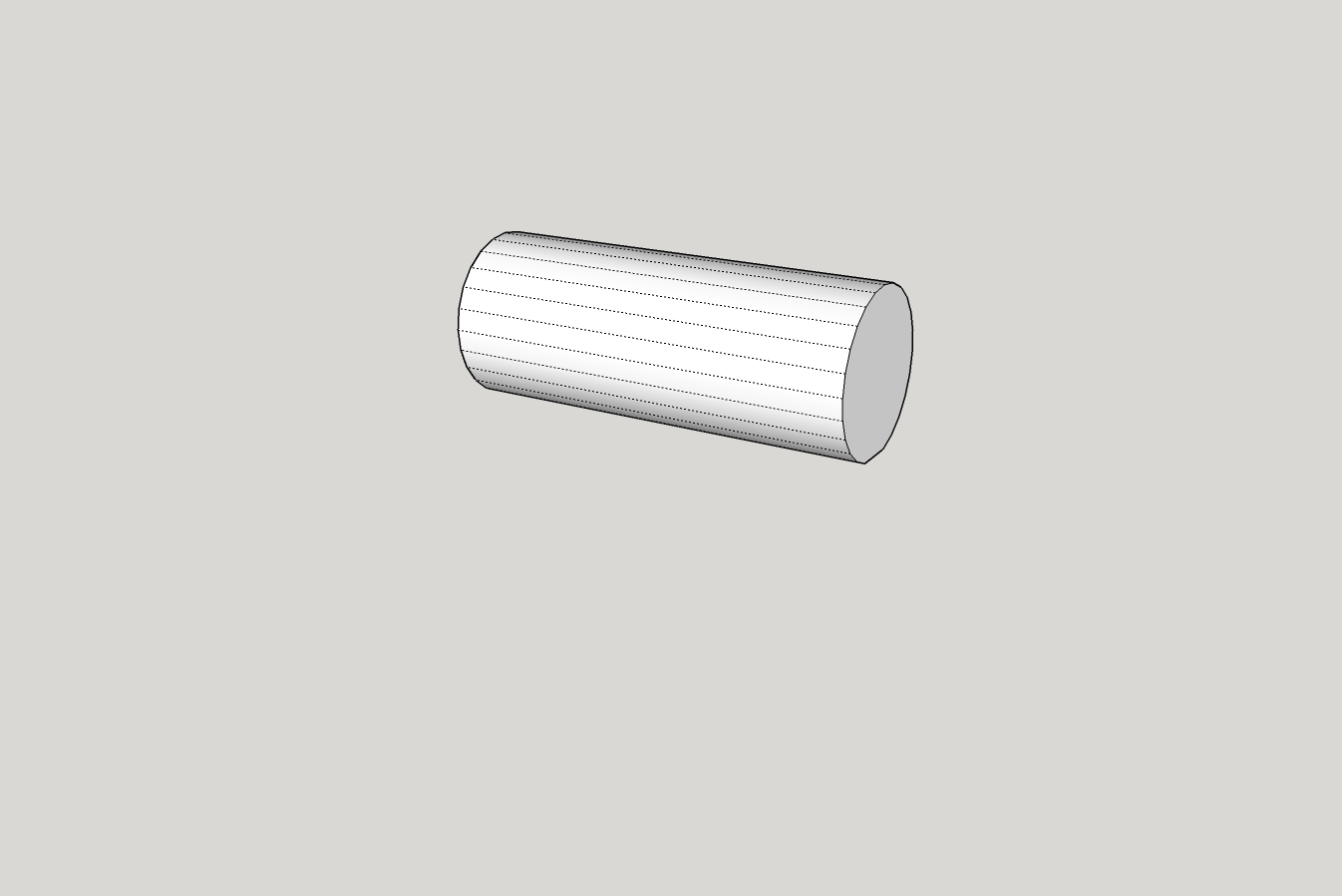
saved as X-Core,
made a copy of the cylinder, rotated it, and placed it into the other cylinder and pulled the ends/faces of the cylinders until I got the length I wanted...
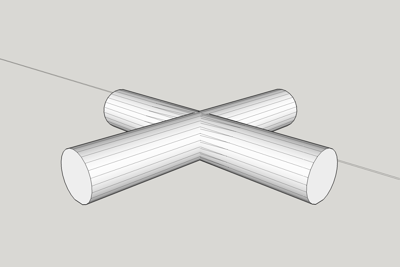
The real problem I had was that when I printed, one cylinder in the model was .0xx above the axis of the other cylinder... it took me a few 'move' operations to get both cylinders on the same horizontal axis in order to print properly... which leads me to ask, is there any tool to 'align' objects to one axis, i.e., the bottoms of the cylinders will lay flat on the build table when built?Once I got the X-Core right I was able to save it as my Tee-Core, push the face of one cylinder into the center of the crossing cylinder and it printed fine.

Thanks for all the help in giving me some clues/tips... I still have a lot to learn (like how the transform stuff works), but at least I think I'm making some headway in rough seas...
-
Hmmm... I'm glad it worked but it seems that it was much more difficult than it should be and in your screenshots, you have some triangulation that really shouldn't be needed.
Do you want just the tee without the extension of the crossing cylinder that you have in your original image and like I drew?
-
@dave r said:
Hmmm... I'm glad it worked but it seems that it was much more difficult than it should be and in your screenshots, you have some triangulation that really shouldn't be needed.
oh ya, getting the two cylinders aligned was very difficult for me... I noticed that 'triangulation' also... when I pulled the faces to make the X-Core that seems to have closed up.
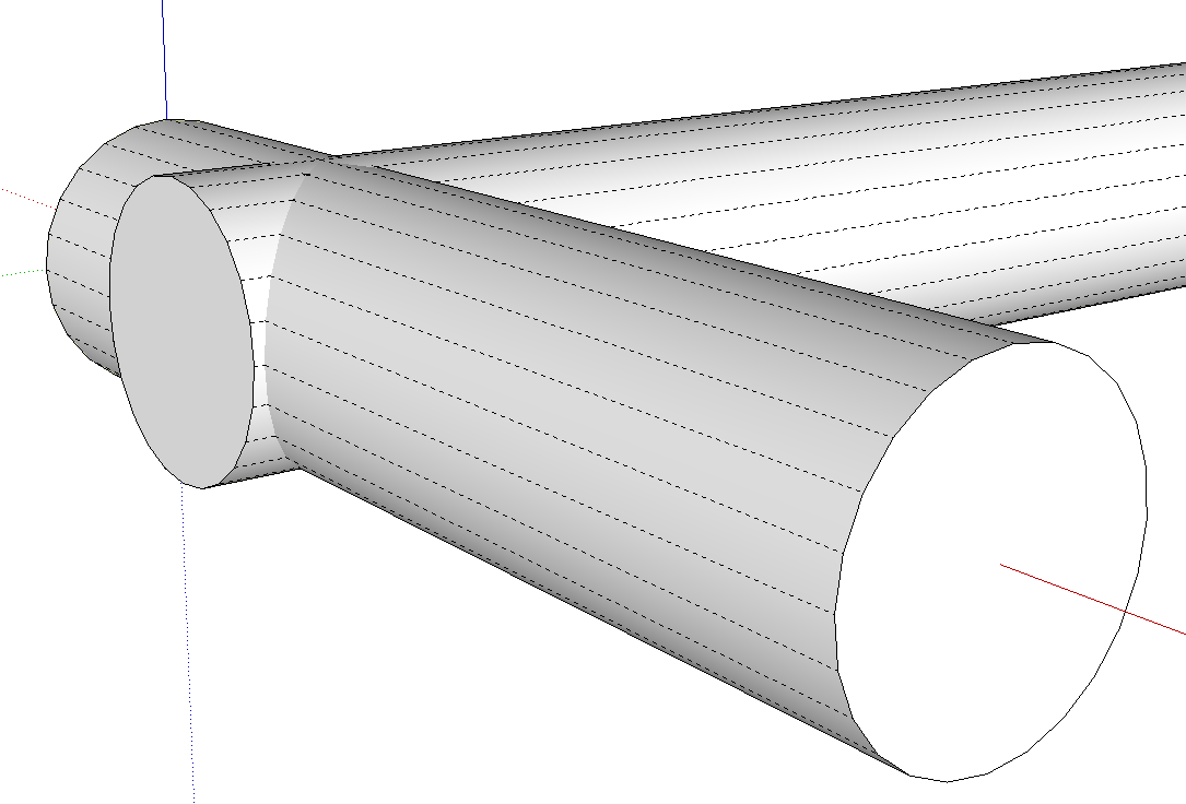
This is what pulled from...
The pics are some of the pieces I need for the 'proof of concept' model I'm working on.
I have to make others that will include adding a ~12[sup:1t7rp2vh]o[/sup:1t7rp2vh] cylinder coming out from the top of the tee... and other variations for a variety of 'connectors'... anyway, although the extra geometry is not needed, the pieces print and that is what I need to get done now. These models are primarily needed to do the sand casting molds, the drawings can be fixed later, if needed.@dave r said:
Do you want just the tee without the extension of the crossing cylinder that you have in your original image and like I drew?
I appreciate the offer... but I don't want to impose on your time... you've given me quite a lot of help already... and I'm sure I'll need more
How 'bout some idea's on an easier way to 'align' pieces?
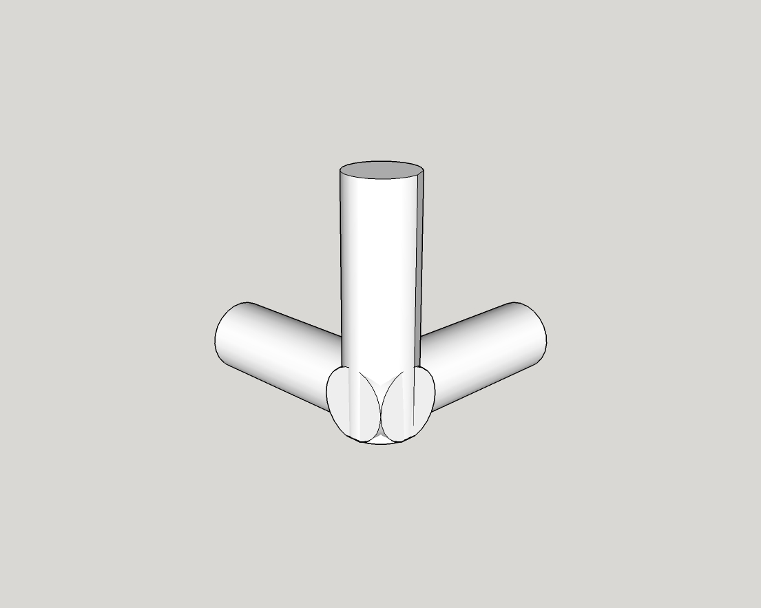
I'm just about to try figure out my outside-corner-tee-with-12[sup:1t7rp2vh]o[/sup:1t7rp2vh]-core... needs to be like the X-Core with one cylinder folded up 12[sup:1t7rp2vh]o[/sup:1t7rp2vh] from horizontal...
-
Alignment shouldn't be difficult. Make sure when you drag out the circle that you are dragging the radius on axis. If you are dragging out the radius of the circles at random angles, you'll be creating all sorts of problems for yourself.
Since the diameter of the tubes is the same, you should be able to simply copy and rotate the first one to make the other part. If you are roating on axis, the alignment should be automatic. When you are moving entities, make sure you are grabbing the entity by a logical point that you can move to another logical point.
-
Thanks, I think I'm getting the hang of it... one thing I find is that when moving an object, i.e., I'm looking at the bottom of one of the cylinders, any slight movement of the mouse to either side shifts the object... I would like to be able to select the object to be moved and then be able to use the up/down, left/right arrow keys to start moving the object and then type in the distance to move, if necessary... seems like until you start movement in a direction I can't type in a value
I did re-do the X-Core and got rid of the 'triangulation'
-
You'll need the mouse to give direction to the move but you can lock the direction based on the axis with right, left, up arrows. If you were able to use the cursor keys to move, it would be in some increment and it would be extremely difficult to make precise moves.
One thing just occurred to me that might be causing you difficulty. Check under Model Info>Units and make sure the box for Enable Length Snapping is unticked. Length snapping would create a problem similar to incremental moves with the cursor keys.
-
Thanks, I'll give it a try. Even though you wouldn't have 'precise' control with arrow keys, it gets you into the ballpark faster and then enter a precise value, imho... guess I'm just used to PhotoShop, Word, methods of moving and modifying images...
Here is my latest variation... may not be the cleanest drawing... but it prints fine
Oh, yes, I unchecked all 'snapping'... everything, move, rotation, etc., still seems to jump and I use typed in value...
Thanks again.
Hello! It looks like you're interested in this conversation, but you don't have an account yet.
Getting fed up of having to scroll through the same posts each visit? When you register for an account, you'll always come back to exactly where you were before, and choose to be notified of new replies (either via email, or push notification). You'll also be able to save bookmarks and upvote posts to show your appreciation to other community members.
With your input, this post could be even better 💗
Register Login


Advertisement