MSPhysics tests and questions
-
Thanks, Anton! This is a great piece of plugin!
-


-
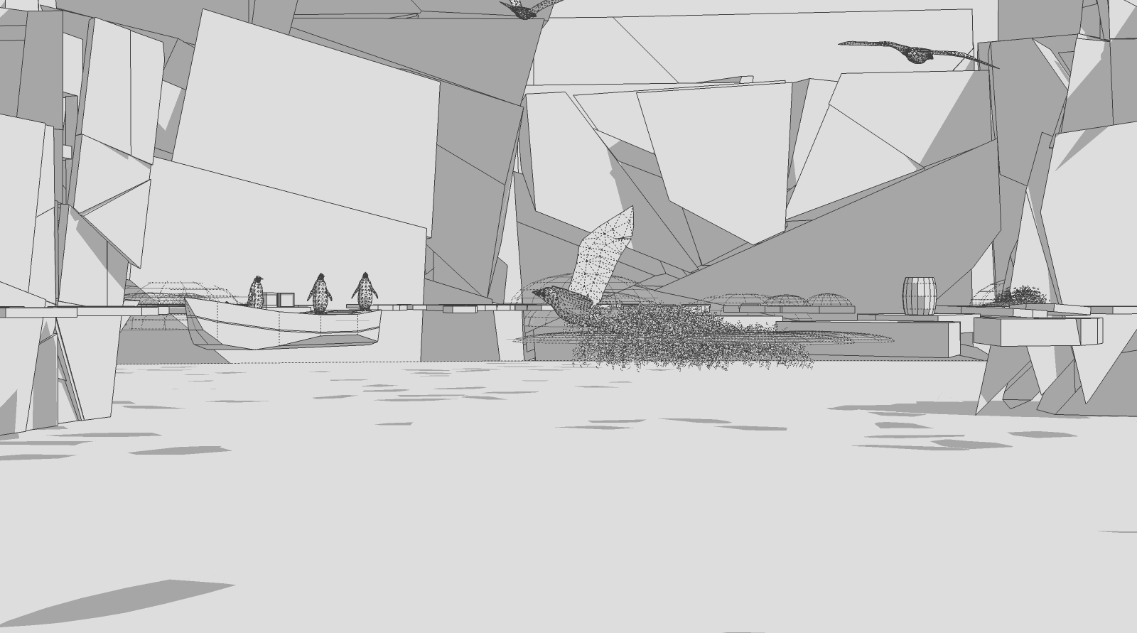
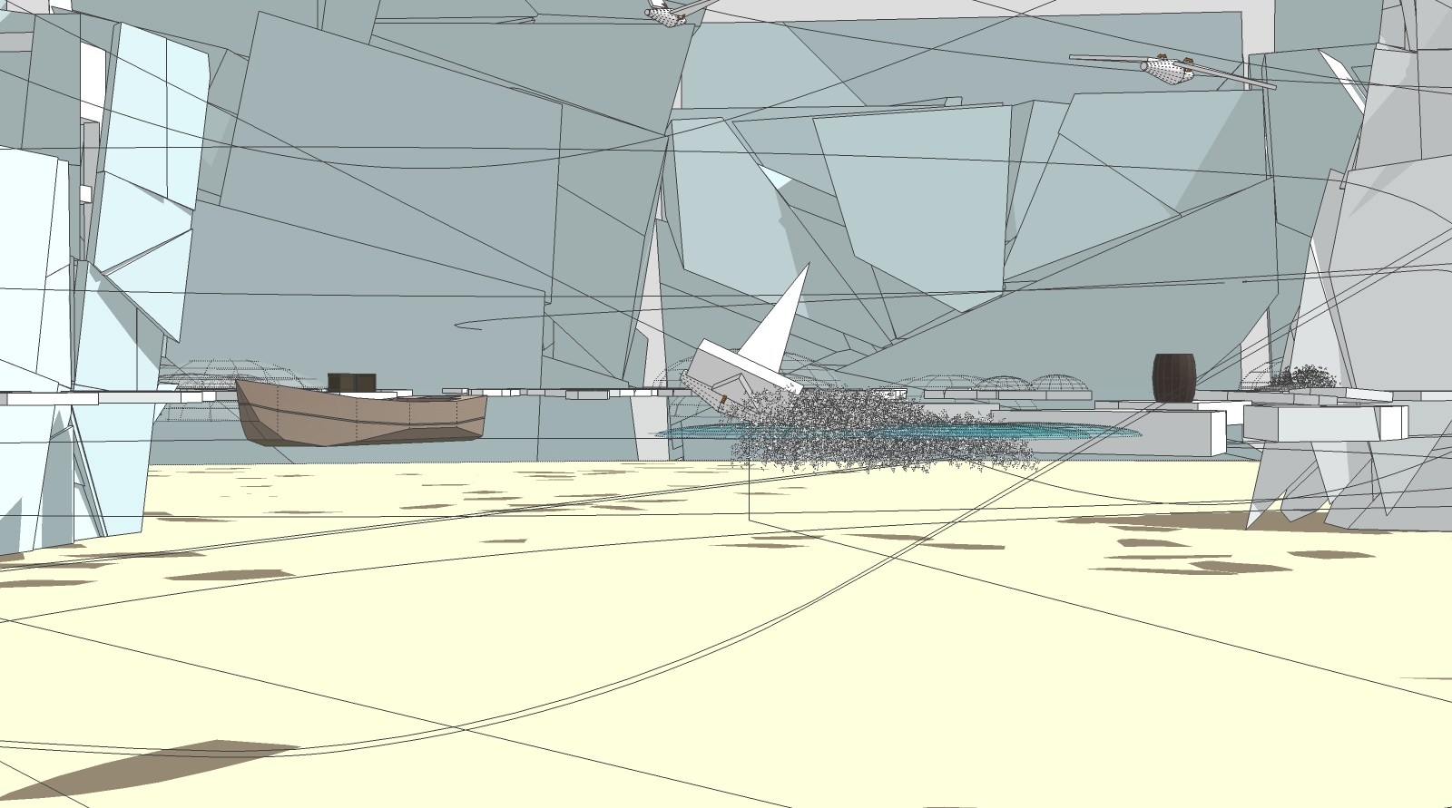
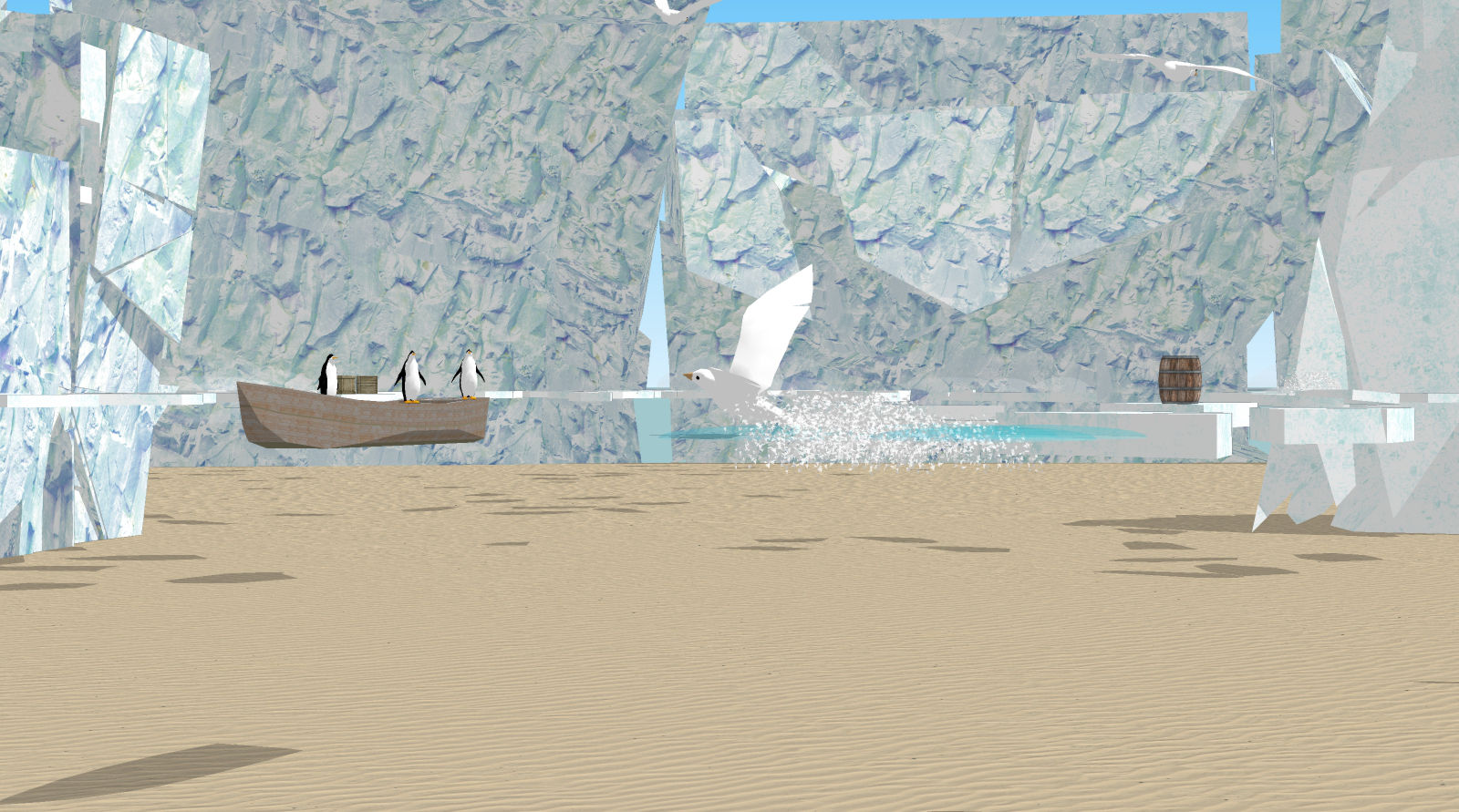
I could not resist to render a new desktop background picture for my PC ...
MSPhysics, indigo RT (path tracing, 7 minutes), removal of the fire flies with image editor.

-
Happy Feet!

-
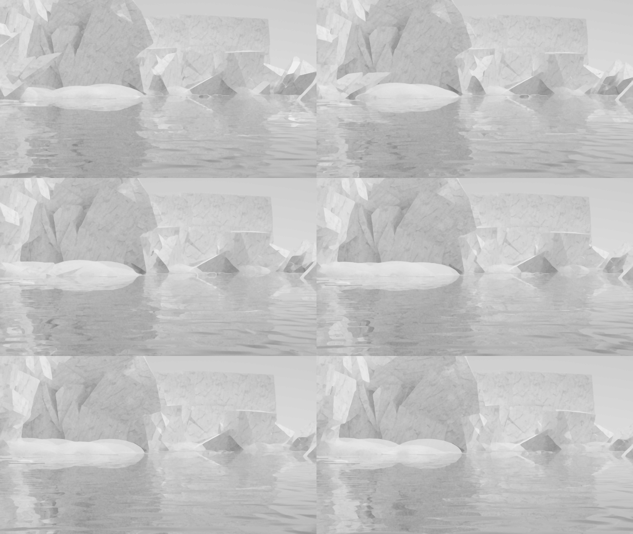
Test model as an example for large replay data stored in the MSPhysics 0.9.2 separate replay file.
The data are produced with onTouch and transforming various emitters to the touch points.
This principle is useful for other physics applications: tire tracks, landslides etc.
The advantage over the Particle effect is, that you can render it.
Please let the simulation run till frame 500 or longer, save Replay, exit the model, load it again and test what happens.

-
Anton, here a long time me nagging question:
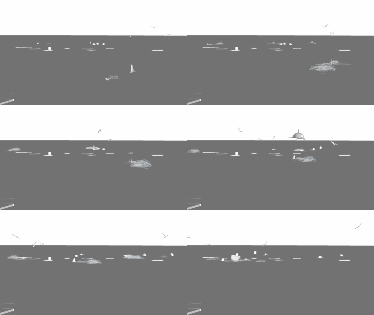
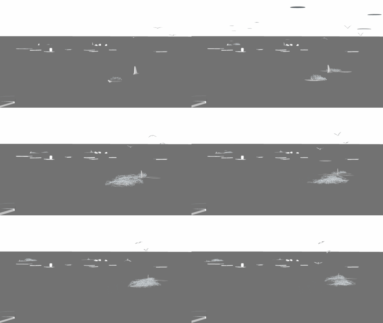
How can I prevent that usually at the beginning of a simulation, transmitted Thruster objects rather accidentally fly into the air at an increased rate?
This initial speed exceeds the set Thruster impulse by several times and can lead to problems with the viewport.
Properties of the initial object are: non collidable, collision shape: Null, Thruster Controller: 30, Lock to Body Axis, Mass: 0.015
Also setting the non-collision per script at the start does not work (onStart { this.collidable=(false) }).
What is the reason for and what can I do to avoid this?
Thanks in advance!
-
How can I use joints or some other way to combine two or more groups/components to form a stiff structure so, that each will have different weight/density and the combined object's center of mass is correct?
My specific problem is that I'm designing a table that has wooden tabletop and steel legs. I'm testing different kinds of steel structures as the legs. Then I'm placing weights on the edges of the table to get some kind of an idea what weight would cause the table to tip over and modify the legs' positioning if needed.
I tried different kinds of joints, but they all seem to make the table to stand no matter what kind of weight I put on the table edge. The only way working so far for me is to use no joints at all, make the whole table a single component and set approximate weight that I calculate myself. But that will cause the center of mass to be incorrect and afaik affects the results of this simulation somwhat.
Any help is much appriecated, thanks!
-
Edit: Duplicate post, see my question in next post.
-
Please post your model (reduced, without textures, scenes, stiles etc.) and we will find a solution.
-
Thanks for the reply faust07. Here's one of my designs, reduced, I hope
 Table design to test what weights cause table to tip over
 -
In this case it seems to be the right approach to take all the parts into a component.
Joints are possible but not very helpful here. (You could test it with the "Fixed" Joint)
What I've changed:
Table legs and feet broken down into individual subcomponents. Then the collision geometry is more accurate. You can see it if you activate Collision Wireframe in Debug Draw in the MSPhysics UI.
The base plate I have assigned the material Concrete and I have the axis position of the cube weights corrected in order to prevent that the parts sink into the ground.
The axes were far outside the cube. But I do not know whether this significantly affect the behaviour of the body.
The best way to prevent sinking is to increase the value for the material thickness (to 0.10) in the UI. Please test it.
-
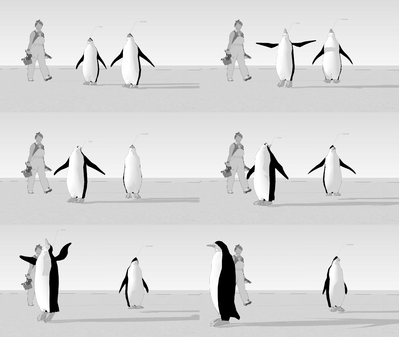
Hi Anton, short question: how can I make up for the differences between controller and scripted input? With the same pre-set parameters why arise the differences in the results?
Model slightly reduced to test it.
-
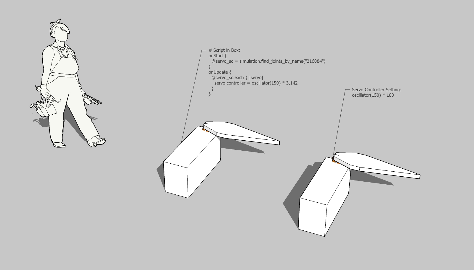
Here is an approximation of the setting of a servo joint (oscillator) with controller or script.
The oscillation about 180° in both directions corresponds to the number pi in the script. Seems somehow to be logical ...
-
Hello faust,
Nice coding there. So, when you assign value via script, i.e
some_servo.controller=, the value is assumed as some angle in radians. Whenever, you assign it via controller, the angle is assumed as the angle in preset angle units, which are by default in degrees.Now, instead of iterating through all servos to assign their controller, a more reliable way would be to use a variable. Control the variable through script and change servo angle via controller. Here is what I mean:
onStart { @p3_head_osc = 30 set_var('wing', 0) } onUpdate { set_var('wing', oscillator(@p3_head_osc) * 30) }Paste this in the controller of a desired servo:
get_var('wing')Other than that, I'm amazed by your improvement in scripting. Keep it up!
Anton
-
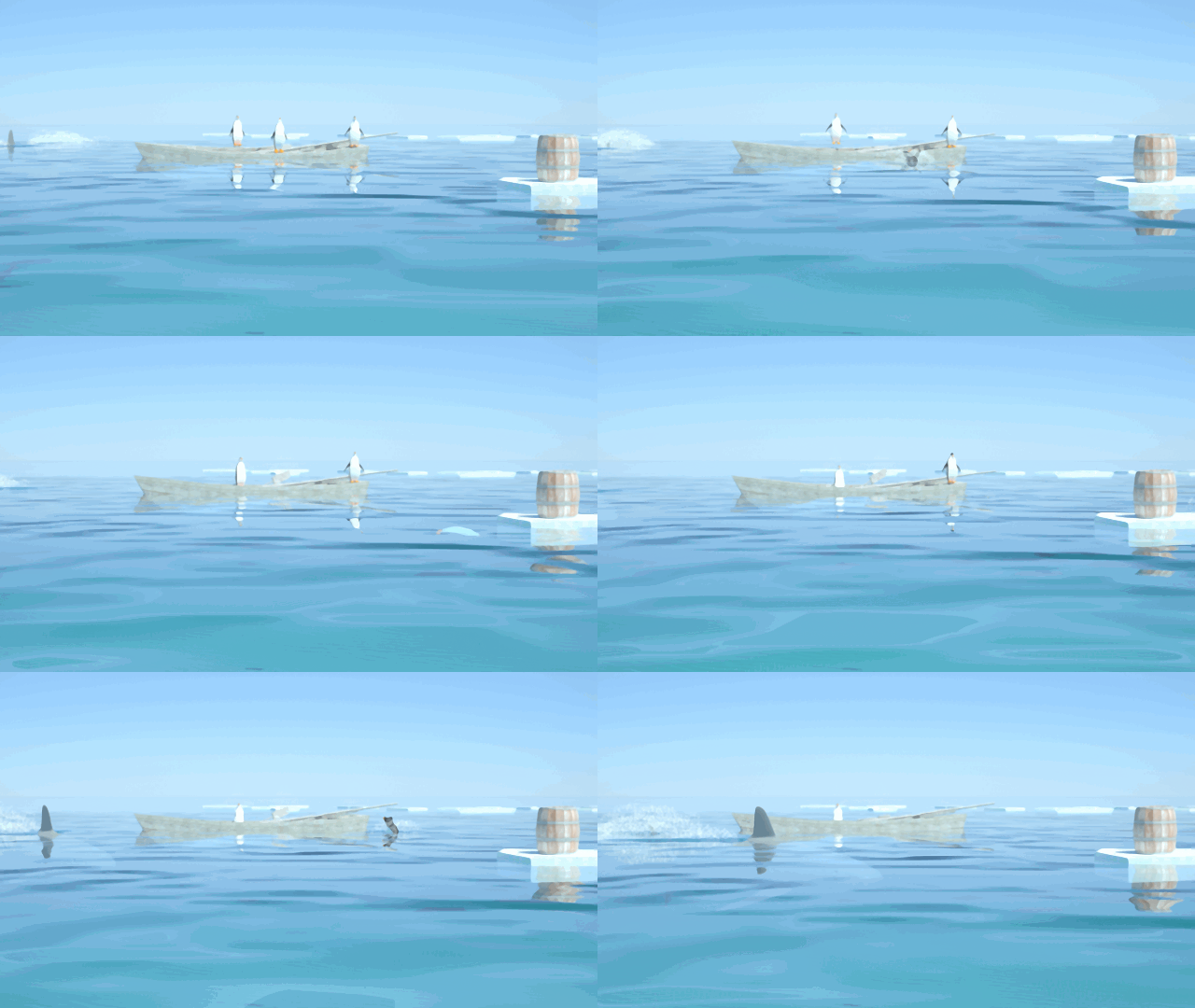
Thanks Anton! The simple way is the best - I will try it. Here a little pengu fun with my old script solution and "Curvy Piston".
-
Hi All
Not wishing to hijack this OP, but I cant see where to post otherwise
so here goes. Attached is a simple falling block assy to test the validity of accel due to gravity, ie block should fall 9.81m in 1 sec, all thing set right.What would be nice is to have a script that stopped the sim once the bloack collided with the baseplate. In theory I should be able to read the time taken, no of frames etc on the bottom lhs of the screen, but just now I approximate this by tapping pause on eyeballing the block - not very accurate at all
Iv'e seen there is an "on touch" script with slamming doors but Im still a ruby newbie
Is there a way to stop the sim on block reaching the baseplate?
FYI If I can get this to work for my students, then the next step is to simulate the viscosity experiment using a falling sphere in fluid, but I dont know if SU can simulate viscous fluid yet?
Great stuff on this page, I am truly humbled
Robin
-
Hi Robint
Put this script into your baseplate (copy the 3 lines, select the plate, open MSP UI, select "Script", paste the lines into the Script window, run MSP):onTouch { |toucher, position, normal|
MSPhysics::Simulation.reset
}and the simulation stops "onTouch".
-
@faust07 said:
Hi Robint
Put this script into your baseplate (copy the 3 lines, select the plate, open MSP UI, select "Script", paste the lines into the Script window, run MSP):onTouch { |toucher, position, normal|
MSPhysics::Simulation.reset
}and the simulation stops "onTouch".
Hi Faust, thanx for the tip, but not quite there yeet
the simulation resets and I lose all the time/frame data at the bottom of screen - which is what I need for this to be useful.
I tried .pause and .stop but they dont exist
Is there something else I could try?
-
Hi Faust
Through the Ruby Code editor, I found a start_timer and stop_timer function
Would this help?
Say put start at the top to activate when staring sim,
then stop_timer after the reset action line
then display timer?
sorry my newbie attempts at script (do you hav any recommendations on the best way to learn script for MSP - there's so much flack out there its hard to know where to start)
Cheers
Robin
-
Hi Robin,
have tested to find a solution to pause simulation per script, but have nothing found until now.
I'm a script newbie too. For my purposes I look into scripts of models from the experts at 3D-Warehouse (AntonS & PituPhysics) or ask them in Anton's main MSP post.
Advertisement


