3D Truss Models
-
Version 1.7.4 - 12.20.2016
- Enabled metal plate connectors for gambrel attic trusses.
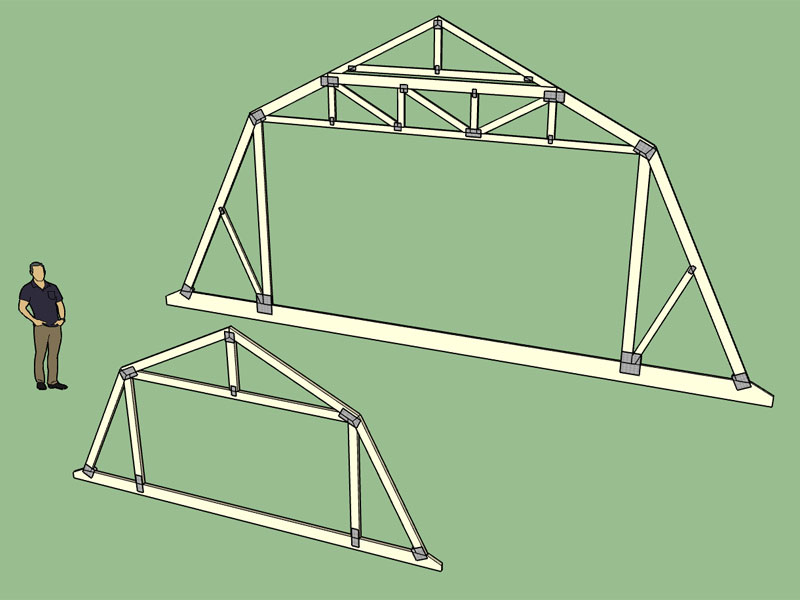
View model here:
3D Warehouse
3D Warehouse is a website of searchable, pre-made 3D models that works seamlessly with SketchUp.
(3dwarehouse.sketchup.com)
-
Merry Christmas to you as well, Nathaniel!


-
Version 1.7.5 - 12.24.2016
- Enabled metal plate connectors for valley truss sets.
- Enabled materials and custom layers for valley truss sets.
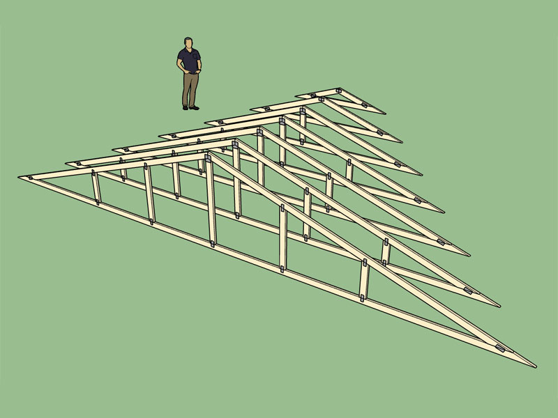
View model here:
3D Warehouse
3D Warehouse is a website of searchable, pre-made 3D models that works seamlessly with SketchUp.
(3dwarehouse.sketchup.com)
Merry Christmas to all.
-
Version 1.7.6 - 12.26.2016
- Enabled metal plate connectors for monopitch trusses.
- Enabled materials and custom layers for monopitch trusses.
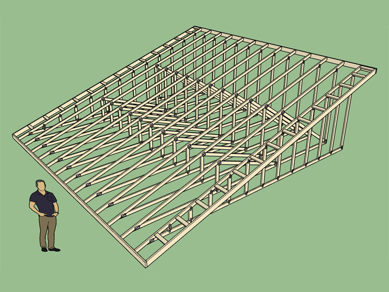
View model here:
3D Warehouse
3D Warehouse is a website of searchable, pre-made 3D models that works seamlessly with SketchUp.
(3dwarehouse.sketchup.com)
I just realized that raised heel option does not work fully with the materials and connectors, I will work on a fix later today to sync that up.
-
Version 1.7.7 - 12.31.2016
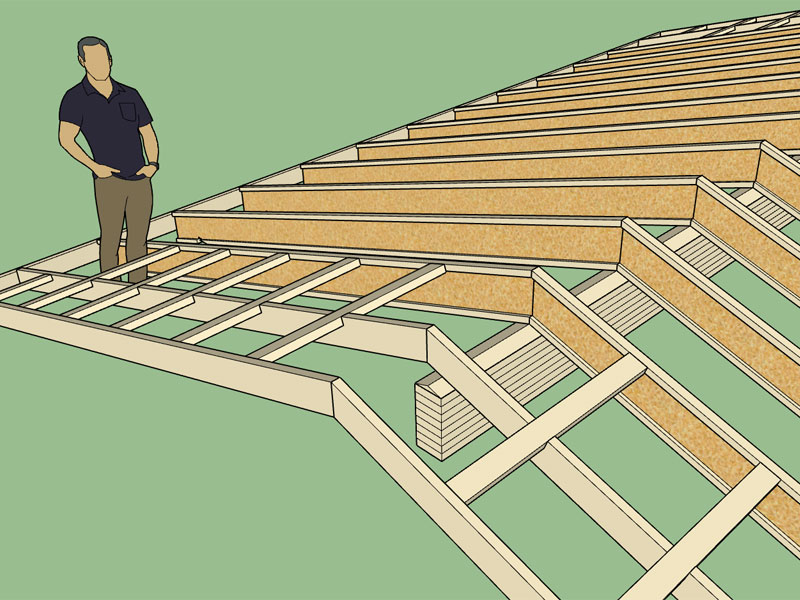
- Enabled materials and custom layers for gable, hip, shed, TJI and dutch gable rafter roofs.
-
Version 1.7.8 - 01.02.2017
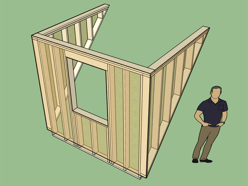
- Enabled materials and custom layers for gable dormers.
- Added advanced options for gable dormers, enabled exterior wall sheathing option.
View model here:
3D Warehouse
3D Warehouse is a website of searchable, pre-made 3D models that works seamlessly with SketchUp.
(3dwarehouse.sketchup.com)
-
Out of curiosity when you architects and designers add hardiplank siding or other types of siding to a building what do you typically do? One could go so far as modeling the sawtooth/washboard of the siding but this would become very heavy in the model. I'm assuming most just use a material/texture to simulate the effect.
On a slightly different note I am looking for a really good texture to use for concrete in my other plugins, any suggestions?
-
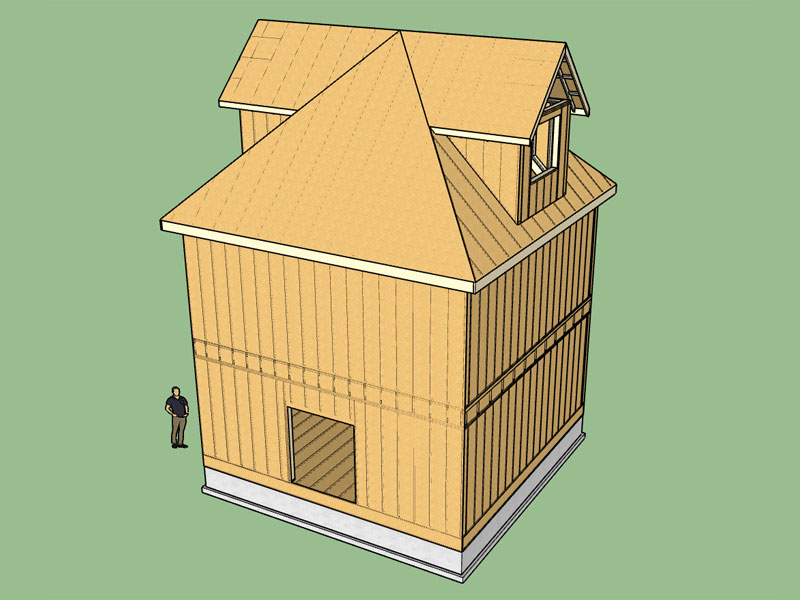
This is an example of custom layers and materials implemented in the Medeek Truss Plugin and Medeek Foundation Plugin and used in one model:
View model here:
3D Warehouse
3D Warehouse is a website of searchable, pre-made 3D models that works seamlessly with SketchUp.
(3dwarehouse.sketchup.com)
Turn off the sheathing layers first to reveal all of the structural framing etc...
Regular walls were created with the Housebuilder plugin.
The trim tool in the Truss Plugin was used quite successfully to manually trim back the dormer roof framing and sheathing.
-
Neck is doing pretty good these days, a little sore some mornings but nothing a little Ibuprofen can't fix.
On the flip side I came off of the Hydrocodone (for the neck and shoulder pain) about two weeks ago but still suffering from the withdrawal symptoms from this drug. My advice, don't ever use Hydrocodone unless it is absolutely life or death, its just not worth it.
I'm trying to figure out what to tackle next.
-
All looking great! Glad your neck is better. (I don't know what you've got or what you've been doing about it: I used exercises on mine which seemed good, along with general exercise. And I use a foam neck pillow. Just in case you're looking for ideas.)
-
Tonight I spent some time trying to do some "real world" modeling and it quickly becomes apparent how limiting the plugins really are. Take a look at this model here:
3D Warehouse
3D Warehouse is a website of searchable, pre-made 3D models that works seamlessly with SketchUp.
(3dwarehouse.sketchup.com)
I need the ability to cut holes in the floors and insert headers and double up joists etc...
There is a serious need for a good staircase plugin, but maybe that already exists, either way it would be handy to have that part of the truss plugin or wall plugin.
Where roofs merge into other walls requires some attention.
I really need to get to work on the wall plugin, I'm using Housebuilder but I have a lot of features I would like to see to make it more flexible and reliable.
The double glulam beam rafter roof would be a nice addition as well.
-
Fixed a small bug in the valley truss set, hence the revision 1.7.8b. Hopefully tonight I can attack the timber truss module, I think I have most of the pseudo code put together.
-
My stair maker plugin creates straight and curved stairs. Also Spirals.
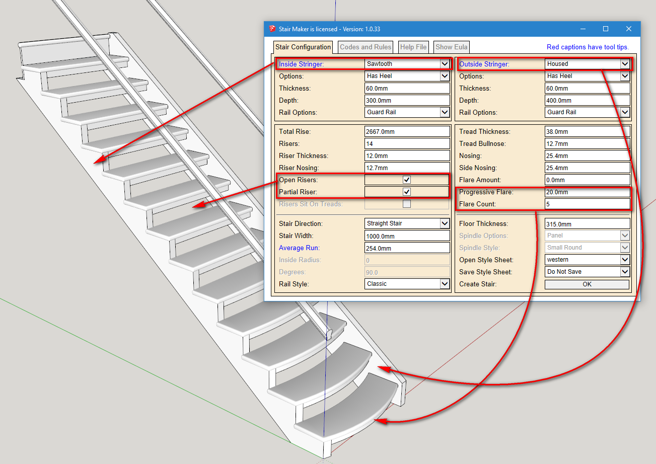
I am intending on adding quarter and half landings and some other features.
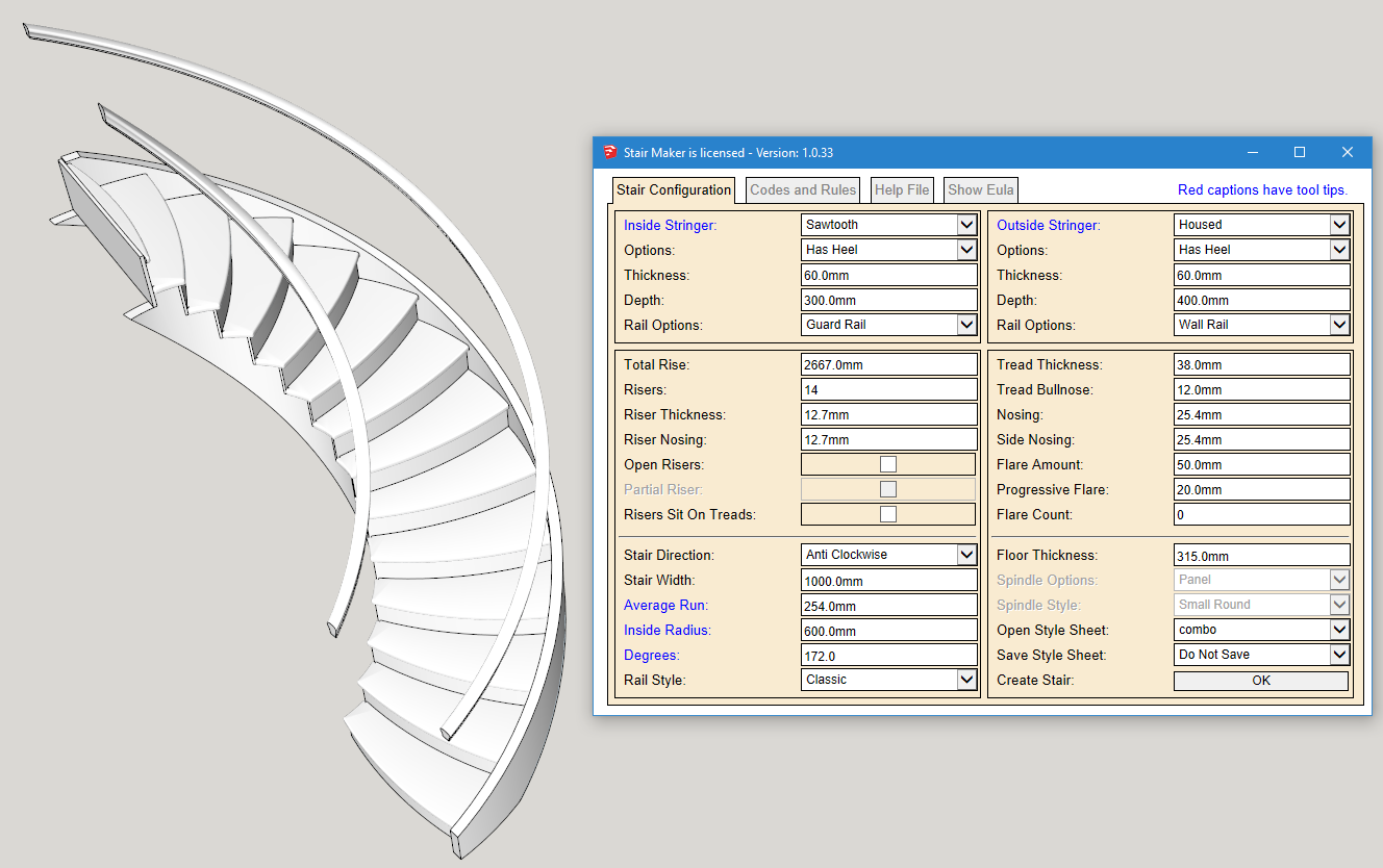
I have built more than 200 of these geometric stairs including elliptical, specialty winders etc.
We also specialized in framed up curved stairs without the cost of stringers.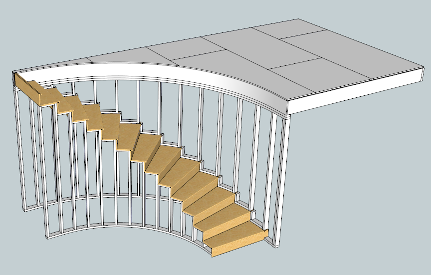
Some of my stairs projects include providing the bending forms and flattened stringers.
-
Spent some time this morning traversing through the common truss code updating some of the truss types so that I can enable energy/raised heels for all common trusses as well as enable custom layers, materials and connector plates.
As I've developed the plugin and added new features I used the fink truss as the cutting edge, so everything having to do with this truss type is pretty much up-to-date, however some of the other truss types are seriously lagging so a little house cleaning is in order.
It may be a few days before I can release this latest version since there is a lot of tedious work ahead.
-
Great work. I wish I had your dedication!
-
I will download your stair plugin and give it a go.
That whole spiral staircase thing looks like a real challenge to code, don't even want to go there.
-
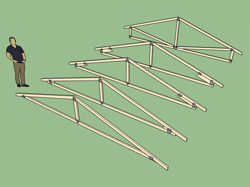
Raised/Energy heels add another level of complexity to the equation. Below you can see that various heights of a raised heel on a simple King Post truss requires different configurations and hence separate plating routines:
This also affects the gable trusses as well, below is a fink truss with its gable counterpart:
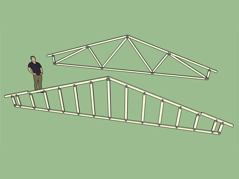
View models here:
https://3dwarehouse.sketchup.com/model.html?id=91d8d78a-8e6c-4dab-9839-4d689c84c297
https://3dwarehouse.sketchup.com/model.html?id=89739563-049f-4277-bfca-75663724967eI'm still house cleaning. I've now got the King Post, Fink and Howe truss fully cleaned up with connector plates enabled for all possible configurations (raised heel, non-raised heel, structural, non-structural). I've only got 9 more common truss types to work through, see list below:
Queen Post
Fan
Mod Queen
Double Fink
Double Howe
Mod Fan
Triple Fink
Triple Howe
Quad Fink -
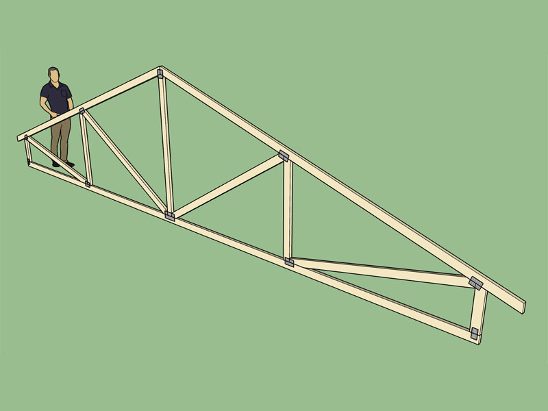
Raised Heel Howe Truss:
-
Version 1.7.9 - 01.15.2017
-Enabled metal plate connectors, materials and custom layers for king post, howe and queen post trusses.- Added energy/raised heels for queen post truss (3 variants: wedge, slider and vertical w/ strut).
- Added energy/raised heels for howe truss (3 variants: wedge, slider and vertical w/ strut).
- Metal plate connectors now enabled for king post, queen post, fink and howe raised heel/energy trusses.
-
I'm still investigating "real world" applications of the plugin to determine where the weakness and deficiencies are. Here is an example combining a dutch gable rafter roof with some raised heel trusses. Now that the raised heel feature is fully active for many of the common trusses it is actually quite easy to measure and then match the heel height of the rafters.
View model here:
3D Warehouse
3D Warehouse is a website of searchable, pre-made 3D models that works seamlessly with SketchUp.
(3dwarehouse.sketchup.com)
I am interested in how others are actually using the plugin and where it is falling down for you, please feel free to send me models or post on the forum with your "real world" design issues with regards to the plugin. This will help drive future development and prioritize the more important items on the todo list.
Advertisement


