3D Truss Models
-
Raised heel double fink truss with connector plates:
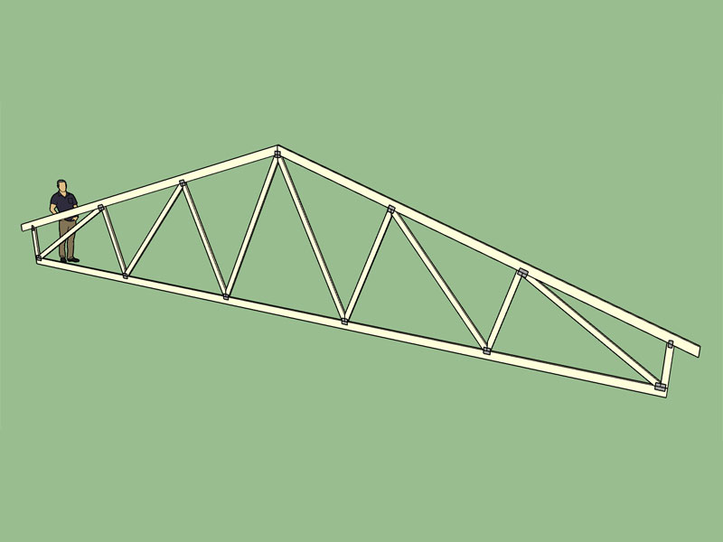
I added this one today and will roll it into verson 1.7.9b.
-
In the advanced options for common roof trusses I currently have the sheathing option. I am wondering if it might be useful to also enable a gypsum wallboard option for the ceiling, with a global setting that sets the exterior wall thickness (inset) and the gysum thickness:
View model here:
3D Warehouse
3D Warehouse is a website of searchable, pre-made 3D models that works seamlessly with SketchUp.
(3dwarehouse.sketchup.com)
Please chime in if this is something that would have some utility or not.
-
@medeek said:
In the advanced options for common roof trusses I currently have the sheathing option. I am wondering if it might be useful to also enable a gypsum wallboard option for the ceiling, with a global setting that sets the exterior wall thickness (inset) and the gysum thickness:
View model here:
3D Warehouse
3D Warehouse is a website of searchable, pre-made 3D models that works seamlessly with SketchUp.
(3dwarehouse.sketchup.com)
Please chime in if this is something that would have some utility or not.
That would be useful! Below are some parameters I would appreciate to help speed up the process:
- board thickness (manual entry, but remembers the last used value)
- offset from walls (manual entry, but remembers the last used value)
- Z-offset, to bottom of ceiling, below tie-beam (manual entry, but remembers the last used value)
- batten sizing (manual entry, but remembers the last used value)
- batten spacing (manual entry, but remembers the last used value)
I like the way you pull out all the stops! I gather the above will also comply to your regimen of being able to preselect the layer assignments?
Something else (more-or-less in line with your train of thought with the above) that would be great to have, if it could be added as well,0 is the ability to automatically generate an extruded plane (extrusion height manual entry, but remembers the value last used) as the roof material. Generally I model these as a box on top of the purlins/roofing battens as a representation of the roofing material, would be great if there were some automation involved here.

-
@medeek said:
If its not too much I will probably also specify two additional layers:
ceiling_gypsum
ceiling_battenCeilings aren't always made of gypsum board, I think we would need to consider an alternative name there? However, as long as the user is aware, this shouldn't pose a problem even if the naming stays as you proposed.
@medeek said:
What is the typical size for ceiling battens in your locale?
typically 38x38mm and 38x50mm is used, depending on truss spacings
@medeek said:
Also with a roof plane/extrusion, I see the necessity with having this addition when one uses battens but what about when there is already a sheathing layer on the roof and no battens?
I would still consider having the option there. Where I'm from, the typical roof construction does not use sheathing, I think I've used it once ever, with RheinZink as final roof material finish... Maybe some of the other people here can give us some feedback here?
-
On a similar note I would also like to create a new section in the global settings for "Sheathing". Here one can select whether sheathing will be an enabled advanced option by default or not and also other default parameters like sheathing thickness (wall and roof separately). My default sheathing material is OSB but in the global settings I will add a toggle between OSB and Plywood.
So far I have not dealt with wall sheathing on the gable ends, leaving it to the user to add their own but I would like to make that an option.
Also with the roof sheathing I would like make a global setting option of coloring the exterior/top face with a pre-determined roofing material if no other roofing extrusion is present, I've got to think about this some more.
My thinking is that the global settings should allow one to setup or customize the plugin so that all of your typical settings are "fine tuned" for you thereby minimizing the effort required when presented with all of the input menus during the roof creation process.
-
Another item I have been putting off is the heel blocking. I'm planning on offering two variants (vertical and angled), with the option to draw in the ventilation holes (typically 2" in diameter in my region, with 3 holes per 24" o/c spacing) if desired:
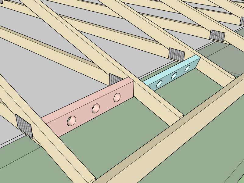
Obviously this is not a hot item since no one has bugged me about it but I have not forgotten it, just put it aside up until now.
With raised heels this may become a bit more complicated requiring more options, (ie. a V-cut instead of the typical bird holes). More input from builders would be useful in this regard.
With the angled heel blocking an overhang must be present for this to work so the code will revert to a vertical heel block when not enough overhang is present.
-
I like what you have proposed here. What I will do is add a new section in the global settings called "Ceilings" that enables one to enable a gypsum wall board layer and/or battens. The thickness and sizes can also be set here as well (which become the default values) but the pop-up menu for ceiling - advanced options will allow for manual entry of each item and will also override the default values with the last values selected.
If its not too much I will probably also specify two additional layers:
ceiling_gypsum or ceiling_sheathing?
ceiling_battenWhat is the typical size for ceiling battens in your locale? and the o/c spacing?
Also with a roof plane/extrusion, I see the necessity with having this addition when one uses battens but what about when there is already a sheathing layer on the roof and no battens?
-
I didn't particularly like the shade of the plywood material that is standard with SketchUp, so I went looking for a better texture. I think I've found one that I like but would be happy to entertain others if someone has a certain plywood material texture that they like.
-
I've got the plywood material working quite well in the plugin, and the ability to toggle between it and OSB in the global settings. I have a few more other features and edits and then maybe I will role a revision tomorrow or Sunday.
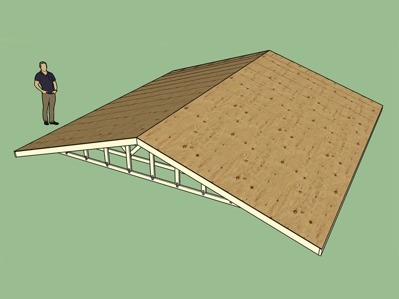
I actually like the plywood look much better than the OSB.
-
OSB or Plywood will now be an option for the floor sheathing:
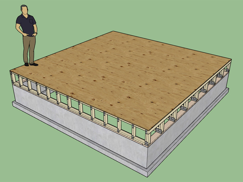
The new sheathing tab in the global settings:
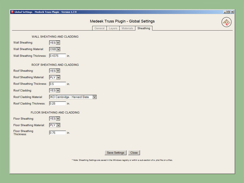
As time goes on I will probably add in more options for wall cladding and interior wall cladding (ie. gypsum) as well as the ceiling logic I discussed in a previous post.
I'm now working on the gable end wall sheathing option and the roof cladding option.
There are also two new options in the "General" tab which allow one to toggle the default setting for gable end trusses and advanced options (roof, floor etc...).
-
Version 1.8.0- 01.22.2017
- Enabled roof cladding for common trusses.
- Added nine "IKO Cambridge" architectural shingle colors into the roof cladding material library.
- Added "plywood" material for roof and floor sheathing.
- Added a "Sheathing" tab into the global settings.
- Added entries in the "General" tab of the global settings to toggle default settings for gable end trusses and advanced options.
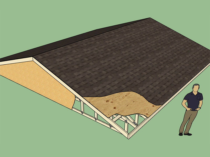
View model here:
3D Warehouse
3D Warehouse is a website of searchable, pre-made 3D models that works seamlessly with SketchUp.
(3dwarehouse.sketchup.com)
Initially I was just going to texture the exterior face of the sheathing for the roof cladding but then I realized that there may be cases where there is roof cladding but not sheathing or vice versa. In the end I went with a separate layer, material and extrusion for the roof cladding, this allows one to get more granular with the structure and in my mind closer to reality.
-
Trying to find a good wood shake or shingle roof texture, this one is pretty good except for a bit of banding:
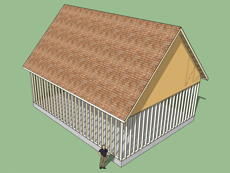
Slipped in a wood shingle roof texture and a few metal ones in to Version 1.8.0.
I set the exposure of the wood shingles at 5-1/2", however it does look a little small to me, maybe 7-1/4" would be better?
-
When you first install the plugin the layers, materials and connector plates are disabled or turned off by default, maybe it would be better that they all be turned on. Either way all of these items can now be customized in the global settings.
-
I am wondering why SketchUp doesn't automatically ship with more high quality textures? This seems like a no-brainer.
-
@medeek said:
I am wondering why SketchUp doesn't automatically ship with more high quality textures? This seems like a no-brainer.
Yup, you know it. I recently experienced a situation where people are starting to create rendering engine textures using 4K and higher images, this was over at Indigo Renderer. Crazy stuff but probably in the not-so-distant future normal.
-
And even if the quality is not so great a few more textures (built in) would be nice. I'm just surprised that there is not more built in textures for roof and siding materials. There should be at least 50-100 such textures (roof and siding specific) built in with SketchUp, or so I would think. This sort of thing could only help SketchUp's marketshare and adoption by serious architects and designers.
-
Yes, more (and better) out-of-the-box textures will be great. However once "serious" professionals start using this for more than just conceptual study modeling, they generally get professional texture packs or collect / make their own.
-
Thinking about sheathing and cladding advanced option for the valley truss set. Typically the valley truss set is placed on top of the main roof sheathing:
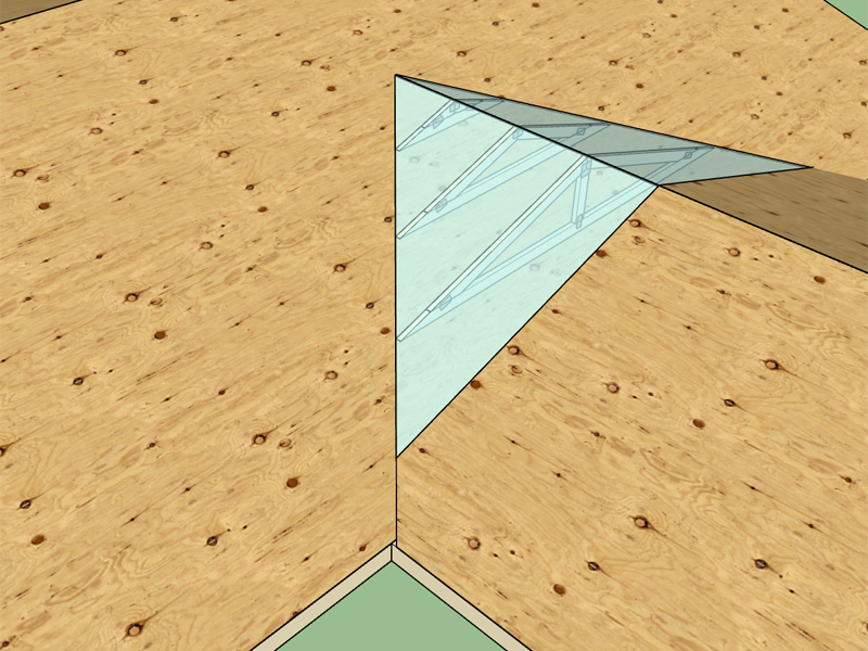
View model here:
3D Warehouse
3D Warehouse is a website of searchable, pre-made 3D models that works seamlessly with SketchUp.
(3dwarehouse.sketchup.com)
If I create the sheathing and cladding just right then it will be easy for the user to manually trim the secondary roof sheathing and cladding with my trim tool and then optionally union them up with the built in Union tool. I may need to make a video showing exactly how to perform this task.
-
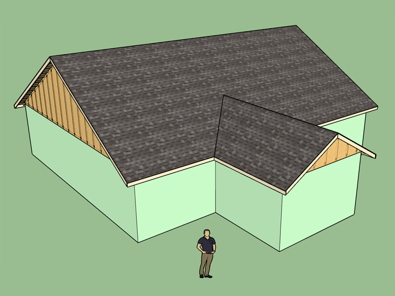
The valley truss set now has sheathing and cladding added as an option. You still have to manually trim the secondary roof's sheathing and cladding and then union it to the valley set's but with the trim tool this is very simple to do:
View model here:
3D Warehouse
3D Warehouse is a website of searchable, pre-made 3D models that works seamlessly with SketchUp.
(3dwarehouse.sketchup.com)
-
Advertisement


