How can I draw a flat rectangle on a non-flat surface?
-
I often need to draw something flat on an uneven surface, e.g. when I sketch up up houses based on sattelite imagery (to give my model some context). I do this by drawing a rough rectangle, perhaps rotate it then extrude. However this is tricky when the terrain is uneven as SketchUp will try to snap the second rectangle endpoint onto the surface below, which results in a vertical rectangle.
The only ways I have found to achieve this is to draw the shape on a flat surface, and then to move it in place. This makes it harder to get the shape right and slows me down, especially when there is no flat surface nearby (large model).
Is there any to disable all snapping after having drawn the first point, or perhaps to force SketchUp to keep my rectangle on a particular plane/axis?
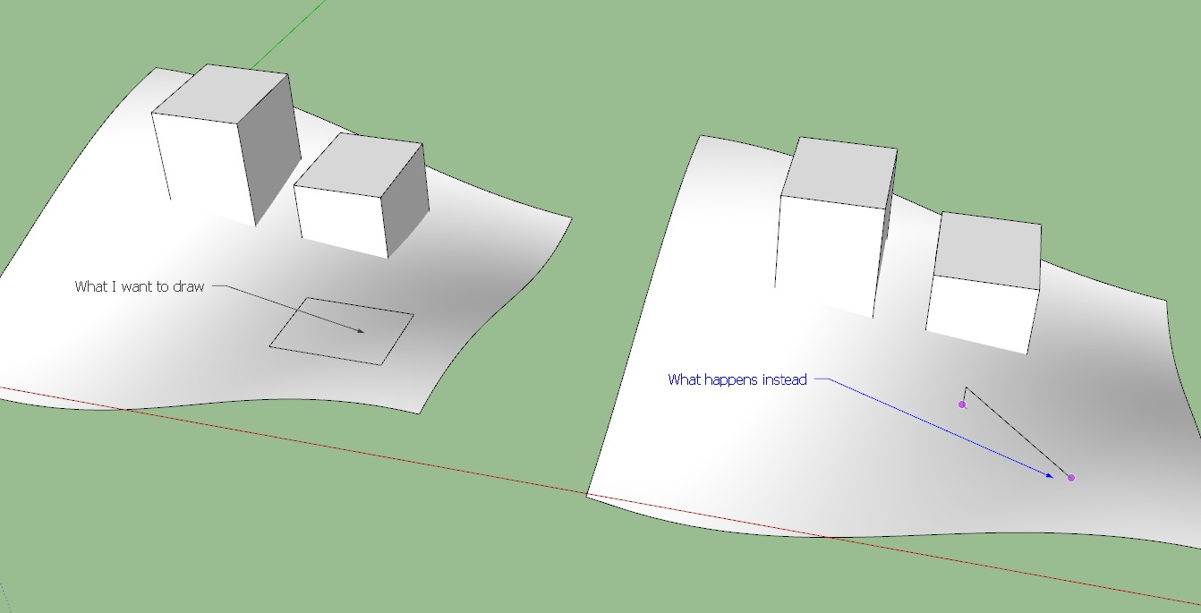
Better explanation on attached file:
-
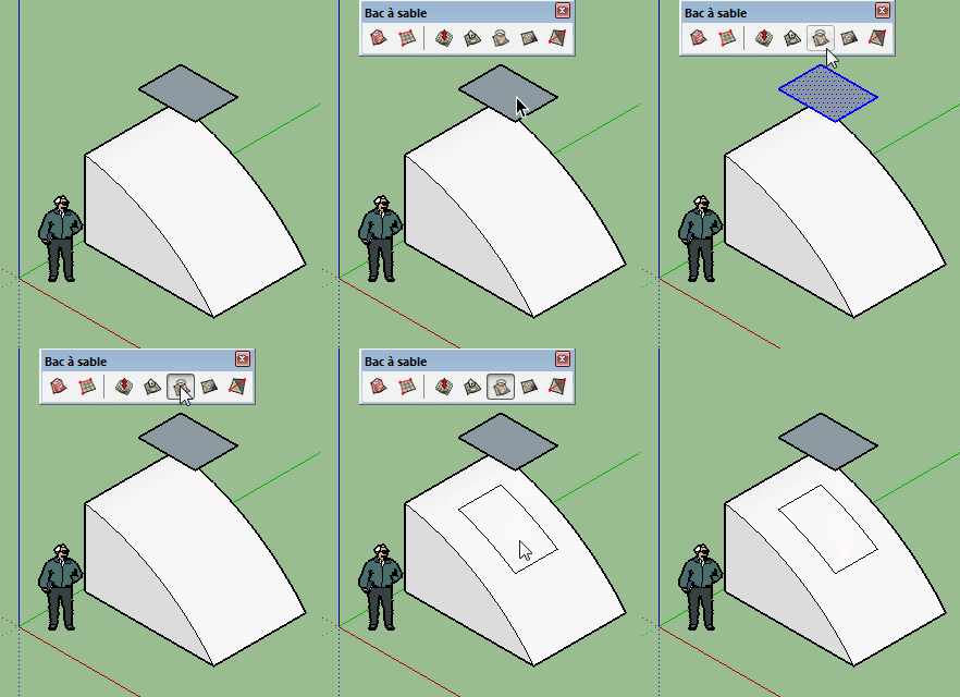
Use the Rotated Rectangle tool for that.
-
SandBox ?
 But Maybe I don't understand the question!
-
Thanks a lot ely862me, the rectangle tool is great. However, I still have the same problem - drawing on an uneven surface results in rectangles that are uneven meaning not horizontal or flat (seen from straight above). The rectangle does not end up flat at all, it tilts the same way as the landscape below.
pilou: No, I explained badly. I don't need to drape the rectangle, I just want to draw it in-place over an uneven surface. So in the example you provided, all I want to do is draw that rectangle where it is shown (or perhaps closer to that curved surface). The first (of two) corner comes up fine, but the second corner of the rectangle inevitably ends up higher or lower than the first corner because it snaps to the surface below.
What I mean to say is, after drawing the first corner I want to keep drawing on a flat plane, which I can only make work on a flat surface.
-
You can't turn off inference snapping so you need to approach this differently. I would draw a rectangle directly above the terrain, paint it with a transparent color and make it a group or component. Then draw your building on that face. If you use Parallel Projection and the top view, you can use the underlying terrain as a reference when drawing the footprints of the buildings. Draw in all the shapes for the buildings first and leave them 2D. Then switch to an angled view and use Push/Pull to extrude them and do whatever else needs doing. After you've completed the buildings, you can move them down to the terrain. That isn't difficult to do manually but there's at least one plugin that could drop the buildings to the terrain.
-
Why do you not create the 'flat' rectangle away from the other geometry.
Then it remains 'flat' as you wish.
Trying to make it 'in place' will only lead to unnecessary complications.
Once its made off to the side [or well above the main surface], you can treble-click it to Select its face and four edges... and then use the context-menu to Group it.
Now you can Select that Group and Move it, by picking some logical point, e.g. a corner, and then snapping it onto the non-flat surface, located exactly as desired.
This way it'll remain 'flat', and it'll not interact with the main geometry.
But if you do want it to interact, then after relocating it... dimply Select the Group and Explode it - its geometry will then merge with the main context. -
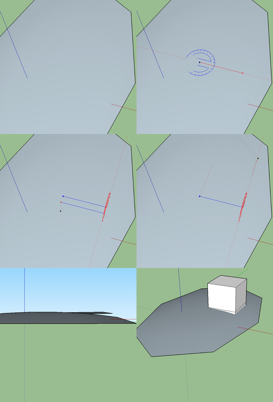
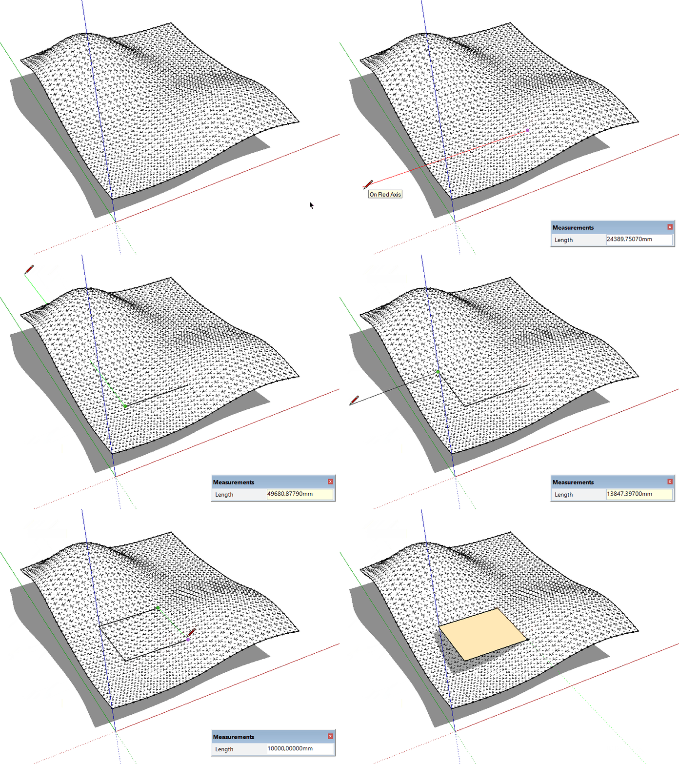
While the tool is selected, click onto the surface while holding the click drag on Z(blue) direction then release it, then press the left/right/up arrow on your keyboard and drag the the first line of your rectangle to that locked direction then draw the other side the same way.
Yet, you can do this with the pencil tool in the same manner.
Click to play !
-
I use the line tool and the axes inference locking in these cases.
-
If I understand correctly, you have a satellite image that comes in with the shape of terrain and NOT a flat version? Hmm. And you are eyeballing rectangular shapes in the image for use in the model. (Not snapping to anything). You just want to go around quickly drawing rectangles that relate to the plan view.
I would draw a large flat rectangle above the terrain/image. Give the rectangle a translucent texture (color). I would go into the default plan view and parallel projection camera. from there you can draw rectangles above the rectangle you see in the image. They will go onto the translucent face.
You can then project the rectangles down to intersect the image/terrain faces. Or you can just move the rectangle down to the height you want it (which I think you said in your second post)
Find it odd you can't get projected satellite image flat on a plane to begin with (as Google has)
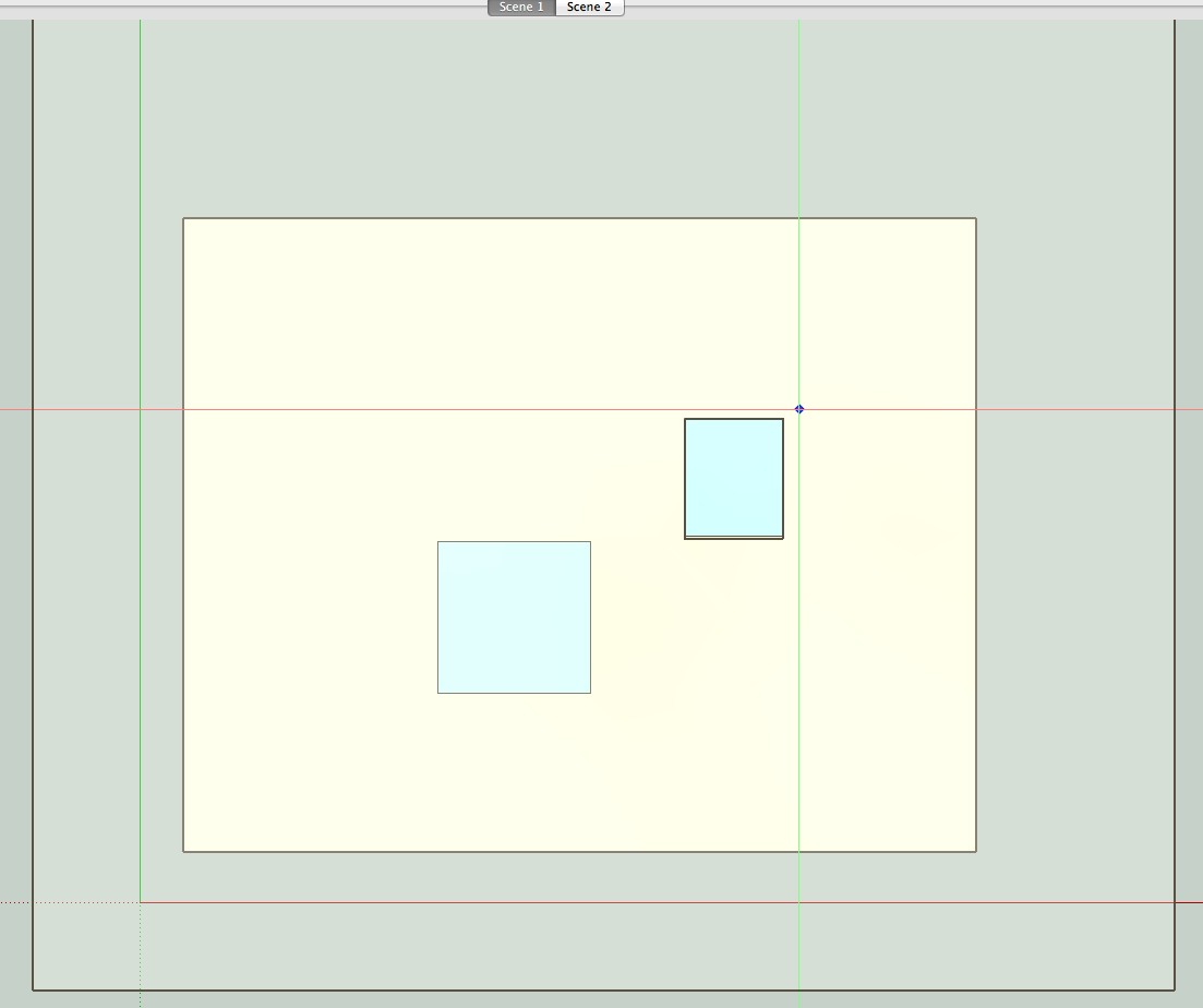
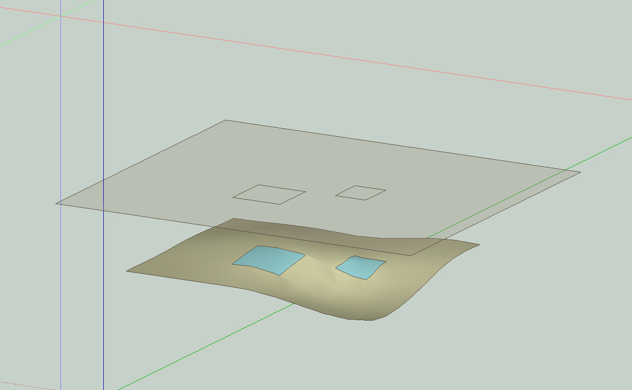
In the pictures the wavy terrain with the blue rectangles represents a satellite image.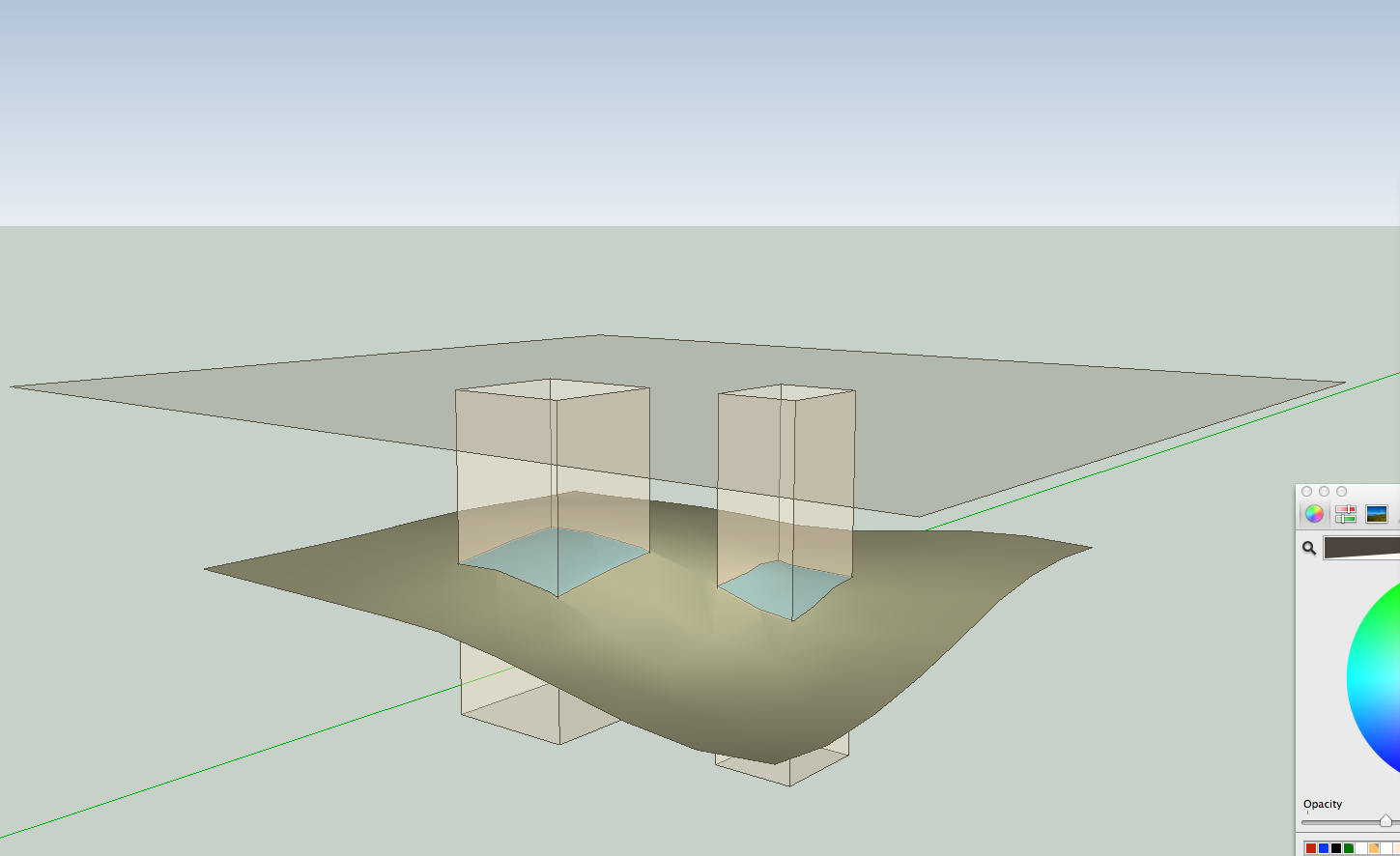
-
@cotty said:
I use the line tool and the axes inference locking in these cases.
A short animation for this...
-
Hi,
Thanks a lot for advice.
I've been using both tricks so far - the pencil tool with shift to lock on axis, and to make a semi-transparent plane far above. Both work but are considerably less convenient than being able to stay horizontal once I start drawing. The problem with axis locking (with the pen tool) is that it becomes very hard to control the length of the line, you pretty much have to type in the length (and it takes longer to draw). The problem with the transparent plane trick is simply that its much work, even with the plugin that lets me automatically drop objects onto the terrain. This is especially when I collaborate in workshops, and want the clients to follow what I'm trying to do at all times. They get confused by constantly switching between 2D and 3D, and the objects dropping from the sky.I didn't expect this to be a standard feature, but it was worth a shot, to see if there are any clever workarounds.
-
So why not use Work plane by Tig ?
Or draw the rectangle above
and in side view Move at the level you yant?
or use Drop Vertices by Tig ?
Or Raytracer by Thomthom
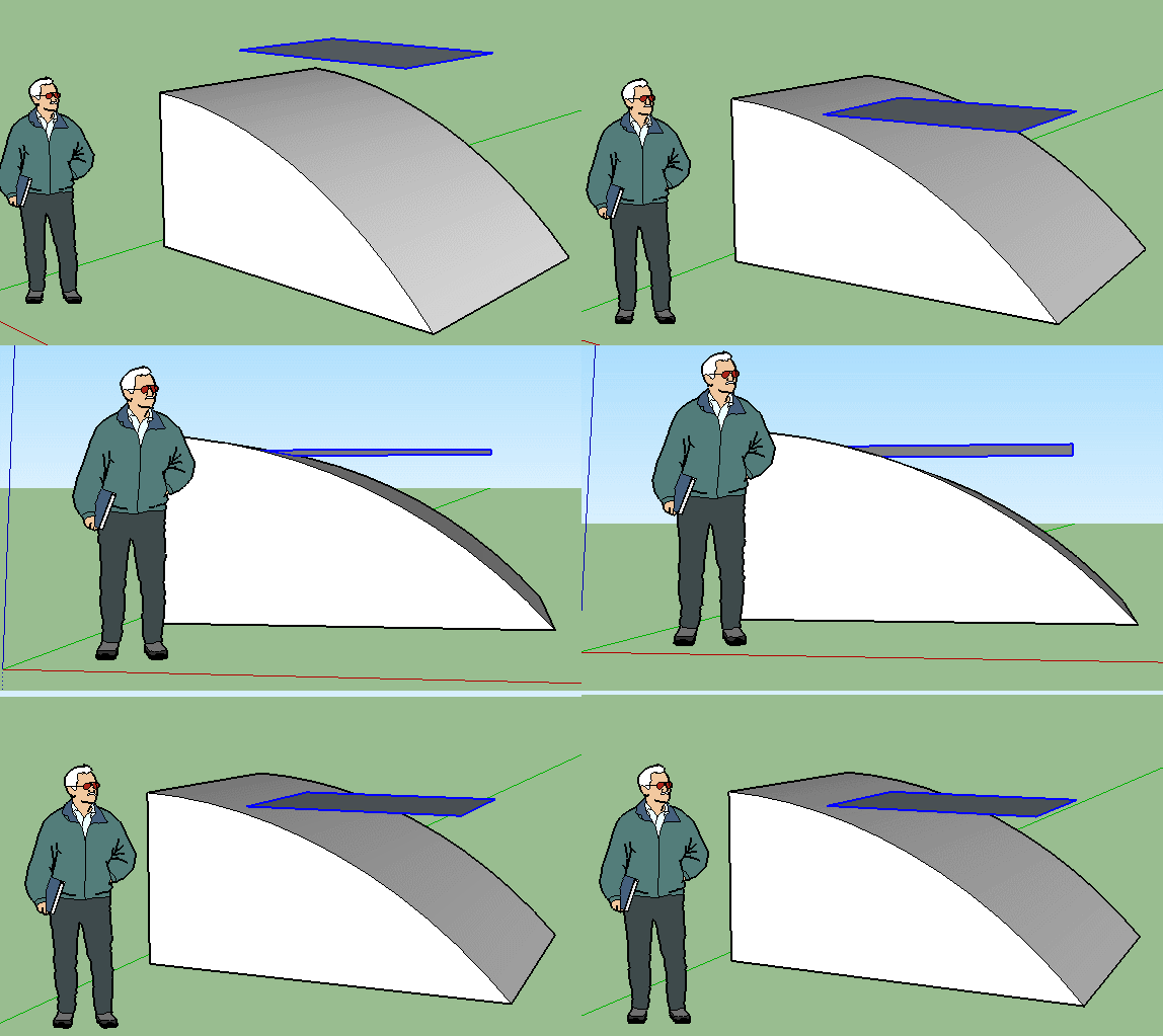
Or this one? By Tak2hata
@unknownuser said:
throw object until they collide with another plane
Advertisement


