Round peg square hole?
-
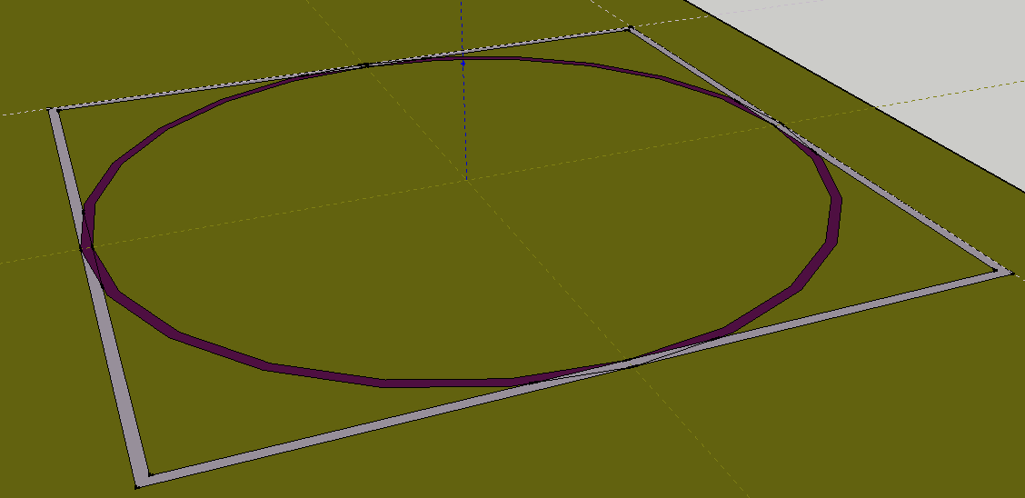
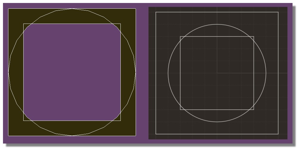
I'm trying to create a simple shape consisting of a hollow cylinder with a certain wall thickness (say it's 10 ft in diameter, with a 6 inch wall, and say 10 ft long) and a square extrusion that shares the same axis as the cylinder and the cylinder circle is inscribed in the perimeter of the square. The situation (prior to any extruding action) is shown in the attached picture. The purple portion represents the base sketch of the cylinder. The grey portion represents the base sketch of the rectangle.
I would like to pull the cylinder wall "up and away" from the green base object, and push the square wall "down and into" the green object.
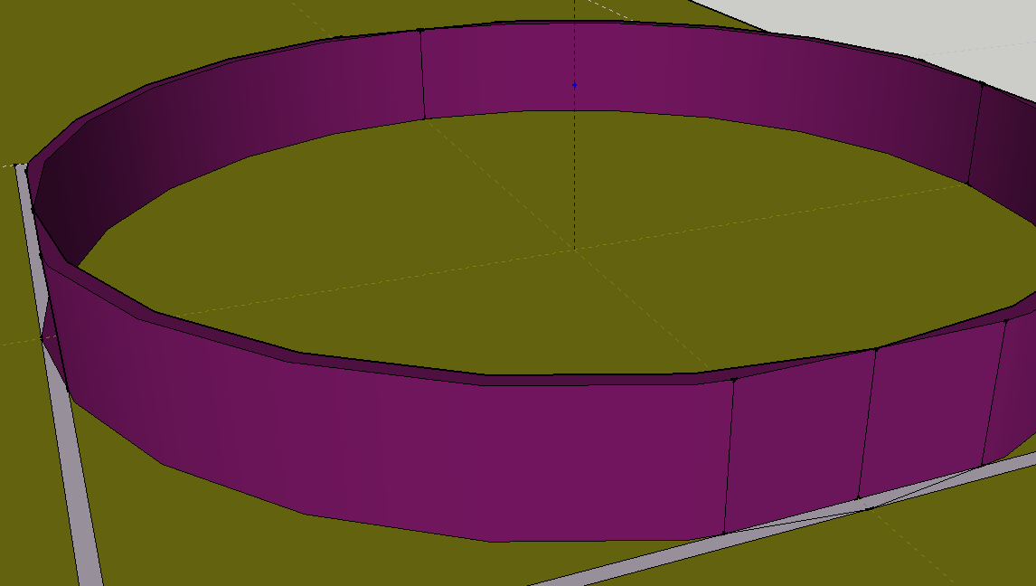
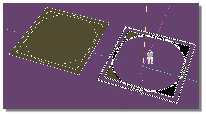
When I go to push/pull either the rectangle wall or the cylinder wall, I get an incomplete extrusion. What I mean by that is that portions of the wall are missing at the place where the two sketches intersect. I've shown an image of the problem in the second attached image.
How do I avoid this behavior? If I start deleting lines, then I have to chose whether the square or the circular portions get to have a complete wall.
Thanks for any help.
-
Hi
One should group objects before adding others , build the base, right click make group, build the cylinder or another object on top, can group this object too if required. Enter either objects and perform push-pull or any other edits as required.When happy and if you want objects to attach and act as one, either explode the groups and make one, or make the groups a group or component
-
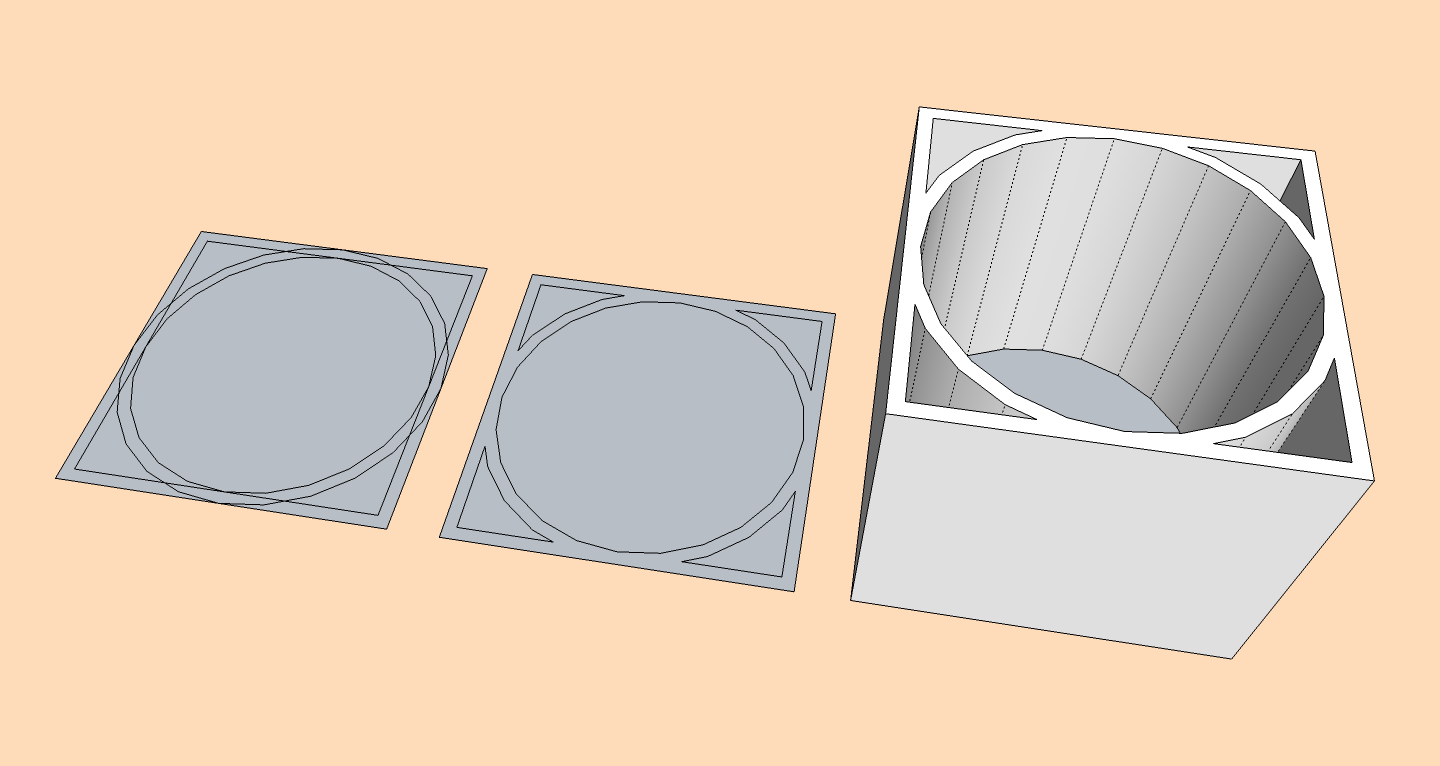
1,2,3...
Is that what you need?
-
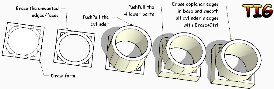
Or perhaps this ?
-
The hole is square and the peg is round. That's the problem

-
And don't forget that Sketchup can't draw real circles!
It's just a polygon! Maybe with 1000 segments maximum!
So very heavy in polygons as soon as you make some operations with them!It's different with nurbs program! On the right!

-
And you can play with the tricky Lattice maker by Tig!
-
@gilles said:
1,2,3...
Is that what you need?
Gilles,
Almost! I just need the box to be extruded DOWN from the sketch plane, not up.
-
@tig said:
Or perhaps this ?
TIG,
Almost, just like gilles! In any case, you have both taught me about the value of fixing up the drawing before I push/pull.
TIG, if I were able to take the form at the end of the sequence you showed, and then move the walls of the cylinder UP so that bottom of the cylinder is coplanar with the top of the square, then I would have the shape that I need.
I'll play with the method you demonstrated to see if maybe I can modify to do what I need.
However, this does seem to bring to light an annoyance of SU that I hope there is a workaround for. Your solution makes sense if one starts knowing the exact shape one is trying to draw - but in my case, I didn't decide to add the "basement" (the square portion) until after I had already put considerable drawing effort into the first floor (yes, I'm designing a house). When I drew the square, its lines intersected with the bottom of the cylinder. If I delete those lines as you suggest, then the cylinder starts losing walls.
I've tried many means of trying to "turn off" the interaction between the circle and the lines (hiding them, putting them on different layers, etc) but SU seems to insist that the border of the circle must be a boundary when I try to extrude the square. Any suggestions?
Thanks
-Ron -
You need to work with groups and components to separate your geometry.
Make the square a component and the circle another component and you can extrude them in opposite directions without interacting with each other. -
@rothloup said:
@tig said:
Or perhaps this ?
I've tried many means of trying to "turn off" the interaction between the circle and the lines (hiding them, putting them on different layers, etc) but SU seems to insist that the border of the circle must be a boundary when I try to extrude the square. Any suggestions?
Thanks
-RonRon,
I am sure TIG will be able to help you out, but let me say that these are not workable techniques. In SU the geometry is connected whether you hide it or put it on other layers (both risky procedures). Use Components or groups to keep geometry separate. Do not put any raw (un-grouped) geometry on any layer besides Layer0. A good way to separate and hide geometry is to make it into a component or group and place THAT on a new layer. The component/ group makes it separate (not affecting other geomentry), the layer makes it possible to hide it. "Hide / Unhide" is a good command for temporary and limited use, but the geometry is still able to interact with adjacent geometry in the same context.
Peter
-
Hiding geometry that is connected to other geometry does not 'separate' it - so it moves/deletes as one thing.
Using different on/off layers for part of some connected geometry also 'hides' it, BUT again it's still connected.
It's a recipe for madness.
Make a rectangular face.
Select the face and assign it to an 'off' layer.
Now erase one of the visible edges.
Now switch the 'face-layer' on - the face has vanished as it depended on the edge that you just erased !Always model raw geometry on Layer0 - have it as your active layer..
To separate parts of geometry use a group [or make a component of it].
You can then hide/layer that 'container' separately from the rest - it is no longer 'connected'...
Geometry that sticks together is very useful, but when you don't what that effect put the geometry inside 'container' groups or components...
Hello! It looks like you're interested in this conversation, but you don't have an account yet.
Getting fed up of having to scroll through the same posts each visit? When you register for an account, you'll always come back to exactly where you were before, and choose to be notified of new replies (either via email, or push notification). You'll also be able to save bookmarks and upvote posts to show your appreciation to other community members.
With your input, this post could be even better 💗
Register Login


Advertisement