Complex roof modeling - need advice
-
Thx : so now the headache will be starting!

-
something like this just on the wires to set each ridge?
http://sketchucation.com/forums/viewtopic.php?f=323&t=50557
I haven't used only just saw your post and then tak2hata's.
might be useful for your landscaping also.
-
To start, your request raises some questions.
-
Are the plan and the plate heights to be considered Bible truth or is there some doubts. I see some things, like the rising ridge you got on one part that makes me wonder. It looks in plan to be something odd there. (This is prior to closer study).
-
All pitches are equal--except some of the connecting parts, ("Crickets")?
-
Any other doubts you have such as equal overhangs?
-
-
Tig has also a roof plugin! (but face by face)
The "volumic roof" in your file is the roof needing ? (seems not many coplanar faces ? )
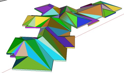
Ps Funny of coincidence of the Tak2hata thread above!


Rainy time so roofs are nedding!
-
I am not sure to understand all the problem but have you try the plug of TIG ?
And the last V2 beta BuildEdge don't work ? (don't work on the v7 so I will try tomorrow)
-
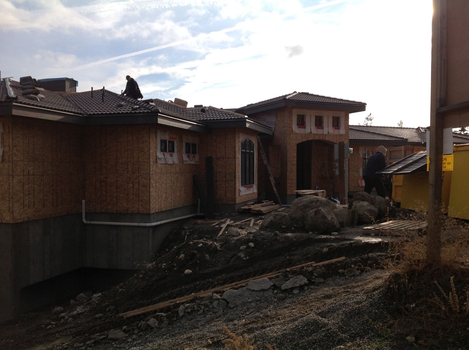
Pbacot - Yes, pitch is 4/12 throughout and consistently except the crickets. Plate height is true to the drawing. Overhang is 2' and fascia height is 12". It's reflected in the CAD drawing in the model. I think the roof is just about done, I'll see if I can wrangle up a photo of the real house going in.
Rich - I was so excited this morning to see the new plugin you are talking about. I was hoping it would just go through and clean up the mess on my face angles, but alas it was pulling verts a bit too randomly. It would great if you could lock one of the verts on a polygon. I'll have to play with it a bit more.
Pilou- I'm well aware of TIG's plugin. It is always my first option. As I mentioned in my original post the "volume roof" you speak of, is one I roughed together to get the idea of how it should work. I know the faces are not co-planar, that is my whole issue. I want to make a roof exactly like that but with clean co-planar surfaces. The logic is just escaping me on how exactly to break the shape up with the varying heights and have it all fit together at the ridge line.
I was hoping and architect or someone with roof design experience could give me some clues. I'm okay with doing it manually, just want it to be clean.
The Vali plugin gets the closest as it represents variable heights, but it keeps crashing on me. I was hoping Build Edge would do it so I bought it today, but it struggled with it. I think it's the weird juncture points between the 45 degree direction change. No sure though.
Thanks for the help thus far.

-
Is it the hips that are confusing?
if it were me, Since each end of the building that will become a hip could essentially be a gable,I would start with your eave overhang, and fascia depth, and knowing that a 4/12 is 18.43 degrees create gable ends first. Then Pushpull them through to intersect. This is going to be a longhand method, and since the fascia heights will vary, and we don't know the heel heights of the truss, you will have to make some assumptions, but if you start with series of gabled roofs, their intersecting geometry will solve what seems like a complex puzzle at the ridges, if you break the house up into solveable roof areas, just one at a time.
The hips are just 45 degree angles that can be created from the gables., and complexities at the eave is geometry that once you have started I believe it will become obvious what it will take to make it work.
I think this approach should work for you. -
Thanks so much Dale.
 That sounds like a logical approach and may make it easier to solve the transitions. If I figured out the height at that angle from ceiling to ridge and drew a vertical line at that height, could I then move that line to all the connecting points along the ridge and connect them to the points along the eaves and still maintain my slope angle? I'll give it a play and report back.
 -
Hi Adam,
I would do all planes manually.
I have downloaded your file and noticed some discrepancies between elevations, plans and your 3D base - this is the first step to a disaster.You need to stick to one element and I would suggest to follow your 3D base - use the elevations and plans to get the roof direction right.
Ignore eaves at the moment - you can extend them later.
PS. I have found one of the box levels to be too low and the roof planes would never 'meet' properly - see my plane in RED - SKP attached.
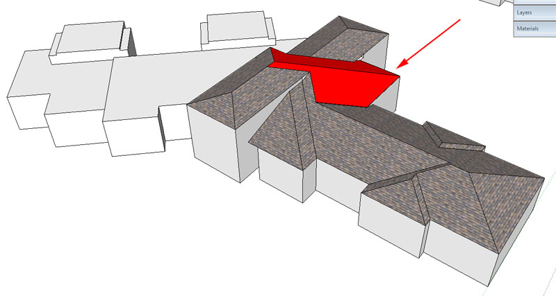
-
Hi Dale, hi folks.
@dale said:
Is it the hips that are confusing?
if it were me, Since each end of the building that will become a hip could essentially be a gable,I would start with your eave overhang, and fascia depth, and knowing that a 4/12 is 18.43 degrees create gable ends first. Then Pushpull them through to intersect. This is going to be a longhand method, and since the fascia heights will vary, and we don't know the heel heights of the truss, you will have to make some assumptions, but if you start with series of gabled roofs, their intersecting geometry will solve what seems like a complex puzzle at the ridges, if you break the house up into solveable roof areas, just one at a time.
The hips are just 45 degree angles that can be created from the gables., and complexities at the eave is geometry that once you have started I believe it will become obvious what it will take to make it work.
I think this approach should work for you.Don't forget that with SU, you don't have to use only decimal angle for slopes.
A 4:12 slope is 18.4349° (approx). It is difficult to enter the exact value that gives 4:12. However, with SU, you can enter this angle as 4:12 in the Measurement Toolbar when using the protractor to orient a guide, for example.
Just ideas.
-
@earthmover said:
Thanks so much Dale.
 That sounds like a logical approach and may make it easier to solve the transitions. If I figured out the height at that angle from ceiling to ridge and drew a vertical line at that height, could I then move that line to all the connecting points along the ridge and connect them to the points along the eaves and still maintain my slope angle? I'll give it a play and report back.
Adam
The main reasons that there will be different ridge heights is a difference in the width of the building, because as you can understand a 4/12 pitch spanning 16' will have a lot less chance to rise than a 4/12 pitch spanning 24', therefore the ridge on the 24' span is higher.
You can deal with this by raising the wall height,(or truss heel) and therefore the ridge, but there is a consequence to this, in that your fascias won't line up, that is unless you increase the overhang on the raised roof.
This of course is a generalization, as is depends on how the faces of the building sit in relation to each other, with a roof everything is case specific.
If you arbitrarily raise the ridge, you will be altering the slope, unless for instance the front plane of the roof is longer than the back plane (1e. salt box style), but the consequence here will be at the intersection of the roof, be it either hip or valley.
Sorry I don't have the time to delve into your model, but I'm swamped at the moment.
I think the key to your roof here is making sure the information you have on wall heights, and building widths is accurate. Then it is just a matter of filling in the blanks.
Oh and as a side note. Dave Richards just PM'd me and told me that if you type the pitch in the VCB 4:12 there is no need for angles. As I explained to him, I've just memorized the angles over the years so it is just second nature to me. So another SketchUp DOH moment. -
Oops missed your post Jean.
-
It really helps to isolate individual geometries into groups when doing a complex roof. I see that roof broken into at least 12 individual groups. When you do this, it is much easier to resolve the intersection geometry. This is especially true if you intend to resolve the resulting ceiling underneath.
-
Thanks gents. Got it resolved for the most part. Learned a ton. Too many roof building plugins around....makes one lose the skill of solving the roof puzzle. It took me really analyzing it and looking at the turns in the ridge. Still not 100% perfect, but it's pretty close.
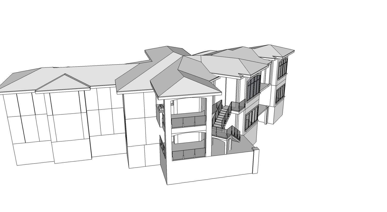
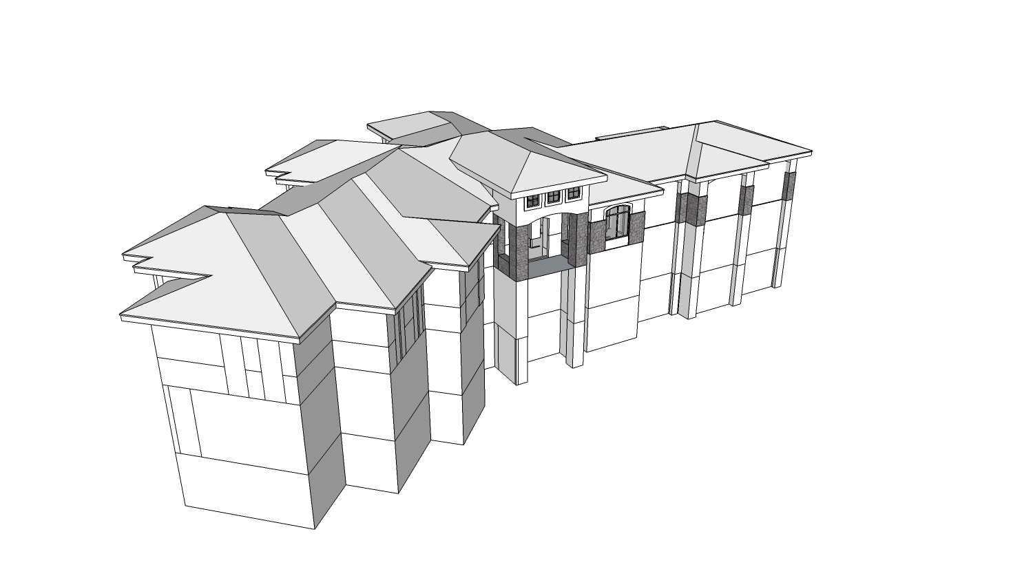
-
Good stuff

-
Good job, Adam. I was going to post some things about "manual" roof modeling and drew some around the garage. But I found some of the discrepancies and ran out of time. Looks like you figured it out fine.
Peter
Advertisement


