Crazy common face
-
Good afternoon, Rich. Seems like afternoon to me although it's only half eight as you would say.

-
Well I would still call it a bug. The face is coplanar and the initial lines are closed.
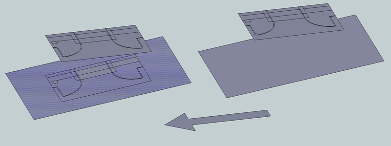
Here is my typical workflow for the sloped landscapes: I import ACAD linework, purge it,
make it perfect, make perfect stand along faces.
Then I extrude lines through the sloped face, intersect it and sometimes I get described above unpleasant result.
Try the attached.
-
Is this a common scenario for you, or have you simplified it for an example? If it's a real situation with geometry being draped on a single coplaner face, why not group the flat CAD edges, move the group on the blue axis until it snaps with the sloped plane, and then rotate it to match that angle? If you have more complex scenarios where you're trying to apply edges to a more complex surface, use the Drape Tool in Sandbox, or TIG's SuperDrape.
-
@unknownuser said:
Is this a common scenario for you, or have you simplified it for an example? If it's a real situation with geometry being draped on a single coplaner face, why not group the flat CAD edges, move the group on the blue axis until it snaps with the sloped plane, and then rotate it to match that angle? If you have more complex scenarios where you're trying to apply edges to a more complex surface, use the Drape Tool in Sandbox, or TIG's SuperDrape.
You are pretty distant from architectural field, aren't you?
By rotating the linework to conform the targeted slope you'd distort the plan view which
has to remain the same. -
Just tried the drape tool- the output is awful!
'Extrudelinetool' ruby is waaay better.
-
You're pretty new to SketchUp aren't you? By extruding the plan view vertically to a coplanar face you distort the geometry. Check the dimensions on the angled face you provided as an example. My rotation example maintains the same dimensions. Unless of course there is some information you've failed to provide to us about what you're trying to do or how this needs to work.
-
@unknownuser said:
You're pretty new to SketchUp aren't you? By extruding the plan view vertically to a coplanar face you distort the geometry. Check the dimensions on the angled face you provided as an example. My rotation example maintains the same dimensions. Unless of course there is some information you've failed to provide to us about what you're trying to do or how this needs to work.
Mate I'd recommend you to check the definition of the 'plan'. And secondly I'm afraid it leads the discussion in the wrong direction. Please believe me, extruding\draping is the right way to develop the right model (from architectural plans).
-
With the example plan illustrated I can not envisage a case when you'd want to do this projected onto a raking surface - what's the purpose...
Perhaps it's just a bad example.
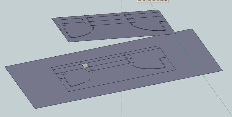
Let's say you had a horizontal "house plan" you might well want to 'project' it down onto a terrain/site surface, as a true footprint.
To help you in this the Sandbox tools has 'Drape' which transfers an 'outline' on the surface [my 'SuperDrape' is similar but replicates the original's materials on the surface below]; Sandbox also has 'Stamp' which transfers the flat outline into the surface an allows you to raise/lower it making angled +/- embankments where fill/cutting is needed... Some of my EEby... tools also do similar things...However, all of this is some miles away from the original post...

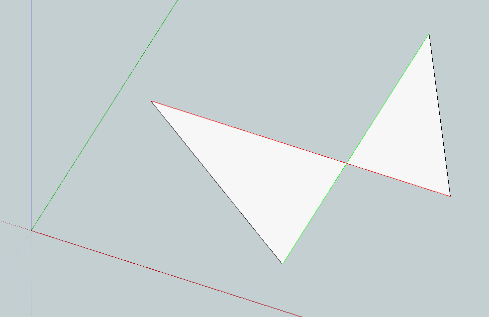
The reason that the 'bow-tie' shaped single face is like this is because it's quite possible to 'cross-thread' the direction of a face's outer-loop edges, as they are initially drawn, swapping from cws to ccws on the same face. Where the edges cross over they will usually initially split, but SketchUp occasionally mistakenly considers them all to be part of the same loop, and forms one face using the whole loop - instead of the more obvious two. This is relatively rare, but erasing the oddly construed face [select+delete-key] and reforming the two hoped for triangular faces, by drawing over just two edges [one in each now unfaced triangle] will usually fix things. Alternatively, erase just one edge to auto-delete the whole face, and then immediately redraw it and also overdraw an edge on the other now unfaced triangle too - this with have have the same result... -
@rich o brien said:
It's not co-planar. If you make it co-planar it will generate 2 faces.
And as charlie says redrawing results in separate faces being formed
I have changed the line color (style) to "By axis" and it seems that the faces are coplanar, because if 2 edges are in the plane z=0, the third one will be too...
-
@tig said:
... this is because it's quite possible to 'cross-thread' the direction of a face's outer-loop edges, as they are initially drawn, swapping from cws to ccws on the same face. Where the edges cross over they will usually initially split, but SketchUp occasionally mistakenly considers them all to be part of the same loop, and forms one face using the whole loop - instead of the more obvious two...
TIG thank you for getting back to original post.

So it'd right to say that Dave R rather recklessly relocated this from the 'SU Bugs' subforum? -
It's a 'feature' of the program !

OK... once it was a 'bug' - however, it was well reported long ago - but they just can't seem to fix it - then it's no longer a 'bug'
it's now a 'feature' 
-
It seems that there is a plugin [$] to solve this problem.
-
Use the query tool to check xyz for all 5 verts. You'll see the object isn't co-planar.
But considering it is 2 tris it shouldn't matter as tris are always planar.
It's a weird one but not knowing how the result was gotten adds to the mystery.
-
It's a rare occurrence.
The 'bow-tie' face...
Usually it appears from CAD imported geometry or some convoluted code-generated faces.
It's hard to make manually, because the default auto-breaking of the edges kicks in as the bow-tie's edges cross over and makes two triangles.
Even settingSketchup.break_edges=falseresults in a bow-tie that doesn't form a face because SketchUp recognizes it as not face-able.
However if you then select just those crossing bow-tie edges and use
Sketchup.active_model.active_entities.add_face(Sketchup.active_model.selection.to_a)it will form a face for one triangle only although the edges forming the loop are longer that the sides of the face
Sketchup.active_model.active_entities.add_face((Sketchup.active_model.selection.to_a.collect{|e|e.vertices}).flatten.uniq)also produces the same odd result.
However, this then Intersects as expected to split the one triangular face off from the unfaced parts of the edges...
I suspect it's a tolerance issue.
The four points aren't quite coplanar enough to auto-split as the edges cross BUT are considered coplanar enough to keep a face
-
@rich o brien said:
Use the query tool to check xyz for all 5 verts. You'll see the object isn't co-planar.
But considering it is 2 tris it shouldn't matter as tris are always planar.
It's a weird one but not knowing how the result was gotten adds to the mystery.
May be I'm missing something...
Look I took original shape and just aligned it to world UCS. all 5 vertices have z=0.000000
(so they ARE co-planar in plain English)
-
When rotated 'flat' the Z value of each of the bow-tie's vertices positions report as '0.000000'...
BUT with a little coding
Sketchup.active_model.selection.to_a.collect{|e|e.vertices}.flatten.uniq.each{|v|p v.position.z}
the 'real' Z values are actually this:-6.93889390390723e-017 1.1518563880486e-015 -1.15046860926782e-014 -2.35922392732846e-016 0.0Note that there are 5 listed because somehow you have managed to split the crossing lines, but kept the one face with all of the edges taken as the twisted loop ! A 'true' bow-tie has only 4 vertices - with 2 crossing edges near the center...So... all Z's are effectively '0', BUT still NOT exactly '0'.
SketchUp has to decide if these are '0' enough for its purposes.
It decides that they are indeed flat enough to keep a face, so it adds one.
However, when it was forming the face it decided that the crossing lines didn't intersect so the lines get just one face with a twisted loop.
BUT then it also decides that the crossing lines DO intersect and it splits them near the center, but it still keeps that one face, when logically it should have split it into 2 !This is rare, but I do agree that it's plain weird...
-
Something isn't correct with that geometry...
If I run Vertex Tool > Make Planar it will immediately make 2 faces. This suggests that the geometry isn't planar and that the tolerance is so small it is outside SU's size limit.
So even though the Query Tool reports all verts are at 0.000000 (6 decimals) the actual position could be 0.000000# (7 decimals or more).
EDIT - TIG reported the discpreancy also. This isn't truly planar
-
That SuperDraped geometry is in effect produced using SketchUp's Intersect methods etc.
Again it's twisting a face's loop and not splitting the face it into the logical sub-faces.
I also suspect that the face's vertices won't be exactly coplanar [resulting from SketchUp's own internal accuracy issues]...
I'm sure we can all reproduce it if we try... BUT the bottom line is that it is fixable at the geometry level with a little work. It doesn't seem readily fixable at the program level.Clearly it is a 'bug' by most common definitions... BUT it's not new, it is known and was reported... However, filing this away in 'Bugs' would get a lot less exposure and traffic than it has where Dave eventually put it...
So as it's not been fixed [or perhaps it's just not fixable at the program level] - so it has become a 'feature' of the program -
...A software bug is an error, flaw, mistake, failure, or fault in a computer program or system that produces an incorrect or unexpected result...
http://en.wikipedia.org/wiki/Software_bug

-
Amen!
Hello! It looks like you're interested in this conversation, but you don't have an account yet.
Getting fed up of having to scroll through the same posts each visit? When you register for an account, you'll always come back to exactly where you were before, and choose to be notified of new replies (either via email, or push notification). You'll also be able to save bookmarks and upvote posts to show your appreciation to other community members.
With your input, this post could be even better 💗
Register Login


Advertisement