Mini-challenge
-
.
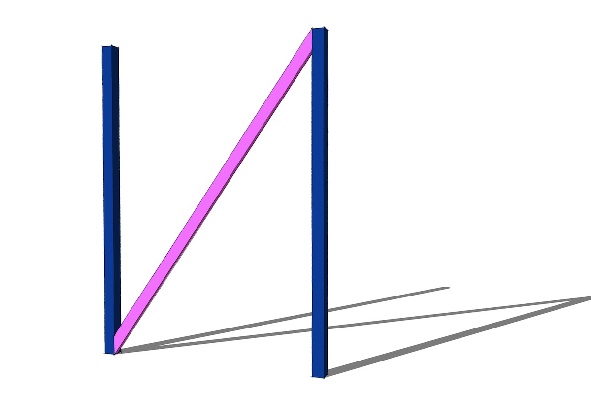
draw the pink board
.
-
Gimme a model?
-
Perhaps I was joking, perhaps not, but what have I got to lose. I'm gettin' out my pen and paper right now.
Something smells fishy around here.
-
@brookefox said:
Perhaps I was joking, perhaps not, but what have I got to lose. I'm gettin' out my pen and paper right now.
Something smells fishy around here.
it seems simple but it's actually hard to pull off in sketchup.
just throwing it out there to see if someone comes up with something more slick than how I've been doing it.
(edit-) as in, my current method isn't very slick.
-
@brookefox said:
Gimme a model?
you can make up your own dimensions as they're not (entirely) important.. (it's mainly about getting the parallel lines of the pink board in there like that)
[EDIT] oh wait, the width_of_ board dimension is critical but you can make that dimension up if you want.. you just have to choose what it is first then draw it..
but here's a starting model anyway..
-
Can you give something more details about this challenge?
-
@ninopiamonte said:
Can you give something more details about this challenge?
you mean like prizes and stuff?
this is a fairly common situation in framing when an X-brace is required.. often, you're able to just trace them onsite but other times you can't (other walls in the way etc..).. either way, it's nice if you just have the right dimensions in the first place..
another example of the same problem.. (2x4 wall frames connected by a brace)
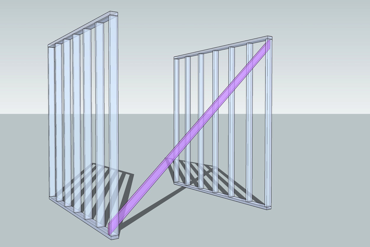
so the the challenge is for you to show your technique (probably via screenshots, .skp, or video) showing the best way you can come up with to draw the brace board in order to obtain proper dimensions for it.
[and i'll act as the judge
 ]
] -
Still not getting it... too early in the morning - haven't had my tea yet.

-
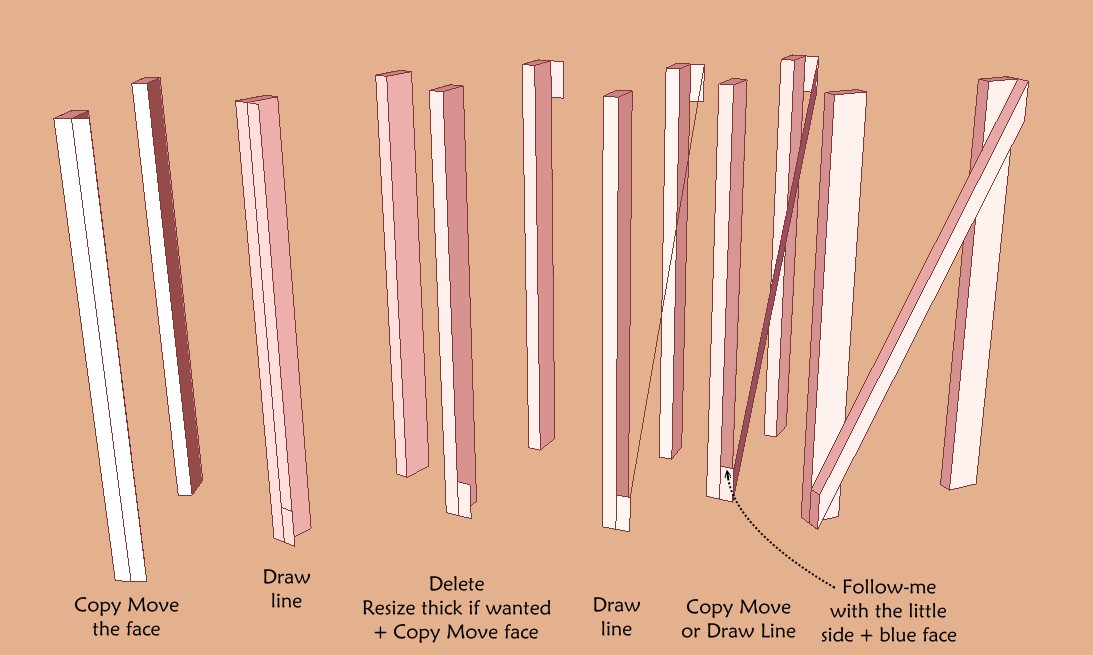
My little try

-
@unknownuser said:
My little try

[attachment=0:259w4kne]<!-- ia0 -->Chall.jpg<!-- ia0 -->[/attachment:259w4kne]
in step 2, how do you know where to draw the line ? (at which height ?)
like i said earlier, your board has to be a predetermined width…
-
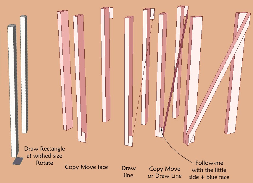
It was made step 3

But if you want better

-
@pbacot said:
I just draw a 2x4 and rotate it then cut with two uprights...?
doesn't work… (unless you're just sorta eyeing it into place.. but this isn't horseshoes
 )
)that's why this is tough
-
It's implicit at my new version above
You have caltulated before the good rectangle for have the good result
-
@unknownuser said:
It was made step 3

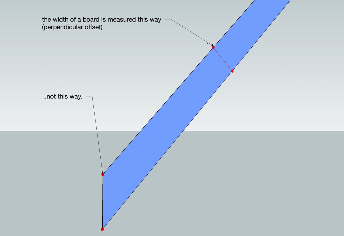
[ie--- the board is a set thickness.. it will always be the same.. the part you're measuring will constantly change depending on the gap and height (angle)..]
-
I just draw a 2x4 or whatever and rotate it then cut with two uprights...? I did that today in a trellis design.
-
Does it has to be drawn correct in the first place?
I was thinking, drawing the profile of the board in the correct size, extrude, rotate it, taper off the ends. - too many steps? -
@unknownuser said:
It's implicit at my new version above
You have caltulated before the good rectangle for have the good result
ok.. i'll try to switch up the way i'm presenting the problem..
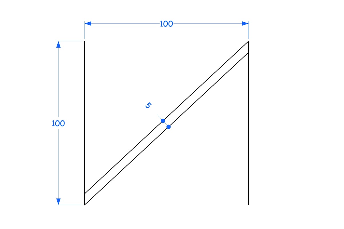
draw this:
(notice which way the 5 units are being measured.. if i measure 5 in the place you're suggesting, my board will no longer have a width of 5.. it will be too skinny)
-
This is an elaborate plugin request - right?
-
Well if you had a true arc or circle you could find your exact intersection points. But there are no true circles in SU.
-
@thomthom said:
Does it has to be drawn correct in the first place?
I was thinking, drawing the profile of the board in the correct size, extrude, rotate it, taper off the ends. - too many steps?take as many steps as needed.. but for you, once you recognize the issue, you'll probably immediate think ruby as a means of solving it.. the way i do it is with a dynamic component.. there's a brute force method to accomplish it within sketchup itself but i'm wondering if i happen to be missing a method.. no solutions given so far will accomplish it..
[EDIT.. haha.. re:your post while i was typing this one
 ]
]
but no.. i didn't set out for it to be.. it's a pretty cool little challenge because of how simple it seems.. hopefully a plugin doesn't jump in too soon and spoil all the fun
Advertisement


