[Plugin] Slicer5
-
Cant seeem to instal Slicer, i put the files in the Plugin Folder and nothing happens.. :s
-
Hebron
Please complete your profile details...
You give me no useful clues as to your OS or SketchUp version etc...Slicer5 is v8 only, with additional options in the Pro version...The current [recommended] version is v8M4
Have you actually read the installation/use instructions?
@unknownuser said:
RBZ
For >= v8M2 you can install this .rbz archive from Window > Preferences > Extensions button [or using Thomthom's 'Simple Installer' tool], the Slicer5 Extension and Toolbar should be auto-activated. Read the instructions...ZIP
For < v8M2 - or a manual install you can extract this .zip archive and place the Slicer.rb file and the subfolder with all of its files intact into the Plugins folder, restart Sketchup. You need to activate the Slicer5 Extension from Window > Preferences > Extensions, the Slicer5 Toolbar may also need to be activated from View > Toolbars. Read the instructions...So how have you installed it exactly ?
What have you tried ?
At what point is it not doing what's expected of it ? -
hi tig,
im working on a model, its a 3d scan with some optimizations, and i cannot slice it with slicer5: it always complaint for "selected object is not a 'manifold' solid"
i was editing the object in blender and sculptris, and theres no problem in those programs.
what am i doing wrong?thanks,
krisztian
-
It's not a solid volume.
Try using TIG's solid solver or Thomthom's Solid Inspector to find the problem.
-
There is nothing intrinsically wrong with using non-solid objects when modeling - provided that you don't want to report true volumes, or to do boolean operations using the 'Solid' tools etc... Some tools rely on the object being 'a manifold solid' for them to work properly...
"Slicer5" needs to make multiple intersections of the object of a plane that steps up/across/through the object... and then for each of those slices it has to decide what is a solid and what is a void, so it can then add faces appropriately to the cut-edges and then pushpull them into 3d slices.
So if the object is not a manifold solid it's going to be possible to intersect it with the plane and on some occasions we'll get a set of edges that won't be able to form a continuous loop, so this in turn can't take any faces and then in turn there is nothing to be pushpulled into a 3d slice.A 'manifold solid' contains just edges and faces, and every edge has exactly two faces - no more and no fewer - so no holes in surfaces and no flaps where some edges have only one face, no faceless-edges, no internal-partition faces where some edges will have three or more faces, and of course no nested groups/components etc which also render the object non-solid [even if they themselves are 'solids' in their own right]. Exceptionally 'Guides-lines/points' are allowed inside a 'solid' but not recommended...
The earlier [much more limited version] of 'Slicer' [still available] did not have the v8 solidity check, and if you were to try it it might offer what you want, always provided that you realize that the 'leakiness' of non-solid forms will never give a full set of 'true' slices...
Non-solids are repairable...
Thomthom's 'Solid Inspector' tool reports on a selected object - highlighting areas where its solidity is compromised.
My 'SolidSolver' tool [get the latest/recent update] tries to fix such issues.
If there are obvious issues like 'large holes' in the surfaces, I suggest you edit it and manually repair those first.
However, 'SolidSolver' can be useful for tidying up the less obvious internal-partitions, tiny flaps and minuscule holes etc... that can all compromise 'solidity'. The more things you have that need fixing the longer the repair might take - some repairs break other aspects which then need fixing themselves etc, and of course anyone can contrive an object with such convoluted non-solidity that after several attempts at a fix it will remain firmly 'non-solid'...
SolidSolver will eventually report [in desperation] that the object is indeed 'irreparable' unless you do some significant manual reworking of its geometry...Also note that if a solid object has tiny facets it might fail to form the intersected edges <~0.5mm and also fail to face/extrude into slices. In that case scale-up the model, scale-up you slicer settings to match, make the slices successfully and then scale-down - the tiny edges/facets can exist but their creation reaches a finite minimum limit as the tolerances can consider two points as being coincident when they are only a tiny distance apart, so no edge is made to span that tiny gap, and of course a face needs a continuous loop of edges to exist so it can't form...
-
Hi TIG,
I have a similar error like pbeseda:@pbeseda said:
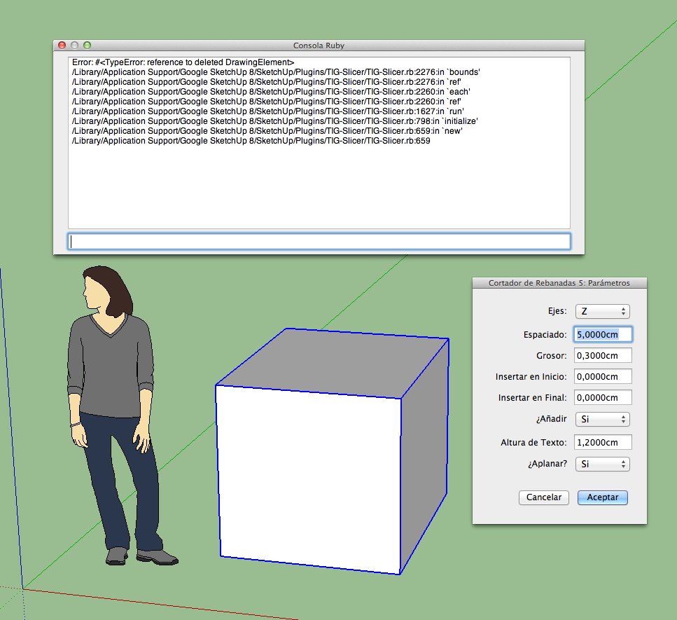
Error; #<TypeError; reference to deleted Face>
> C;/Program Files (x86)/Google/Google SketchUp 8new/Plugins/TIG-Slicer/TIG-Slicer.rb;2041;in `pushpull'
> C;/Program Files (x86)/Google/Google SketchUp 8new/Plugins/TIG-Slicer/TIG-Slicer.rb;2041;in `fatten'
> C;/Program Files (x86)/Google/Google SketchUp 8new/Plugins/TIG-Slicer/TIG-Slicer.rb;2041;in `each'
> C;/Program Files (x86)/Google/Google SketchUp 8new/Plugins/TIG-Slicer/TIG-Slicer.rb;2041;in `fatten'
> C;/Program Files (x86)/Google/Google SketchUp 8new/Plugins/TIG-Slicer/TIG-Slicer.rb;2035;in `each'
> C;/Program Files (x86)/Google/Google SketchUp 8new/Plugins/TIG-Slicer/TIG-Slicer.rb;2035;in `fatten'
> C;/Program Files (x86)/Google/Google SketchUp 8new/Plugins/TIG-Slicer/TIG-Slicer.rb;1612;in `run'
> C;/Program Files (x86)/Google/Google SketchUp 8new/Plugins/TIG-Slicer/TIG-Slicer.rb;793;in `initialize'
> C;/Program Files (x86)/Google/Google SketchUp 8new/Plugins/TIG-Slicer/TIG-Slicer.rb;657;in `new'
> C;/Program Files (x86)/Google/Google SketchUp 8new/Plugins/TIG-Slicer/TIG-Slicer.rb;657
This is my Console Ruby Error:

I work on Mac OSX Mountain Lion 10.8.2 and SU Pro v 8.0.1517
-
Here's v5.14 http://sketchucation.com/forums/viewtopic.php?p=374969#p374969
It adds a submenu item to activate/deactivate its toolbar without having to search through the View>Toolbars list...
It also traps errors that can occur with the Outline option etc where tiny edges can fail to form properly [size related issue].
Now if they do fail then the tool continues, so now the outline might have a few tiny bits missing, but the tool doesn't 'crash-out'.Oxer: I hope this addresses your issue.
If not, then try Scaling everything up x10 or x100, doing the 'slotting' [making due allowance for the size changes], then Scaling back down to the original size.
The small geometry can exists, it just has problems in its creation.
By now we should all be aware of the tiny edge/facet creation issues, which prevent some native-tools and also some scripted equivalents from successfully making very small geometry... -
@tig said:
adds a submenu item to activate/deactivate its toolbar without having to search through the View>Toolbars list...
Clever, I'd never had thought of such cool feature

-
Thanks TIG, I'm going to test the version v5.14.
EDIT: The same error message in the Console Ruby with v5.14 -
TIG
thanks for the update! -
@oxer said:
Thanks TIG, I'm going to test the version v5.14.
EDIT: The same error message in the Console Ruby with v5.14
Can you post the SKP or PM it if you like... with details about what you are trying to do [settings etc]...
Have you noted the issues about smallness?
It can also apply to largeness too...
SketchUp/OpenGL can't cope with very tiny or very gigantic geometry and some edges/facets can fail to form... Also have the objects miles from the origin can also cause issues.
Obviously I'd prefer that my tools don't 'fail', but sometimes it's the nature of SketchUp and not my code.
If I can see the issue first hand I can perhaps see if I can trap for such errors better, or at least advise on the best way to model to avoid the issue... -
It's a very simple geometry, a cube and you can see the settings in the image below:

Perhaps there is a conflict with another plugin, i'm going to uninstall other plugins.
-
The following are the usual suspects [messing with base-class/methods ill-advisedly etc]...
SketchyPhysics [current version]
Podium [some earlier version]
SunPosition [all versions]
Matchbox [all versions] -
I have uninstalled all plugins except Slicer.rb and the problem persists, don't worry TIG, i'll use SliceModeler.rb
-
@oxer said:
I have uninstalled all plugins except Slicer.rb and the problem persists, don't worry TIG, I'll use SliceModeler.rb
That's not the point!
Are you using Slicer5 or Slicer - I am confused ?
Can you please PM a copy of the SKP that has the problem, and the settings you are trying to use...
This ought to work without issues ?? -
New Sketch Up user. Having difficulty installing on apple OS X running free Sketch Up 8. Do you have instructions posted anywhere on the steps.
-
So my aim is to use this tool to create corrugated cardboard furniture. The pieces will be cut and glued together. Should the spacing be set to the same as the thickness. Will this slice the pieces so that they lay face to face.
Also, when slicing it is prompting me if I would like to "Add the Outlines of Adjacent Slices ?" What does this mean?
-
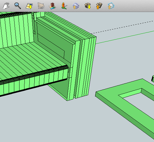
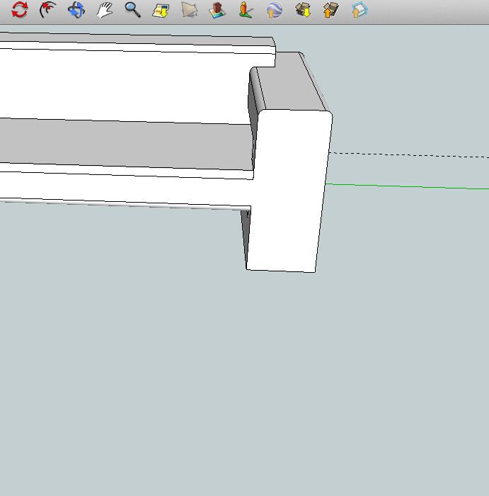
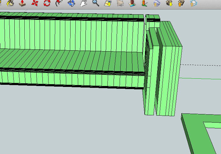
Any idea why I am loosing slices? Seems to be doing some odd stuff and loosing data. See the attached photos.


-
@tig said:
Are you using Slicer5 or Slicer - I am confused ?
Can you please PM a copy of the SKP that has the problem, and the settings you are trying to use...
This ought to work without issues ??I have used Slicer always but like the last version don't work for me i use SlicerModeller v1.3 now.
SKP file and settings that i'm using:
SU file and settings.zip
Remember I work on Mac. -
Excuse me, excuse me, excuse me TIG!!!!


The problem were that I haven't installed the font txt_____.ttf
this happens to me for not having read the first post entirely.
Excuse me again TIG.
Advertisement


