How would you model this (well)?
-
I'm trying to do a very detailed model of a very simple faucet and am having some issues.
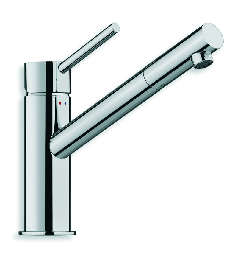
Here's the faucet
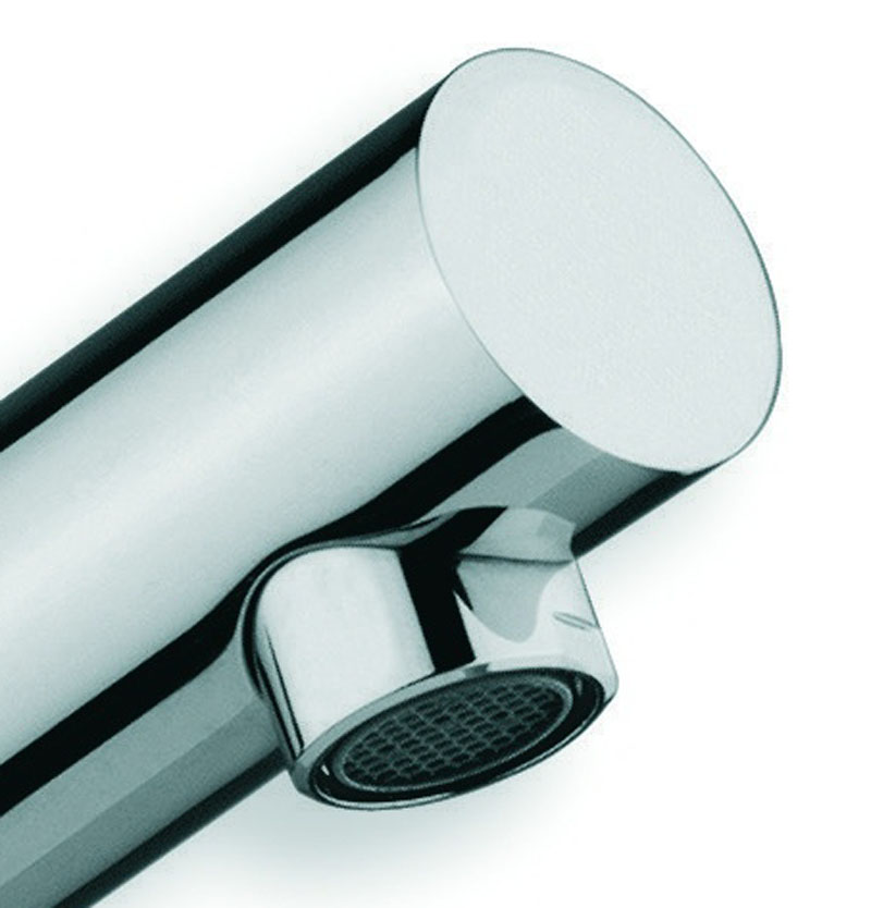
Here's a blowup of the problem section. The issue is the little bevel and curved portion where the main cylinder receives the small cylinder.
Here's the mesh before I intersect the two
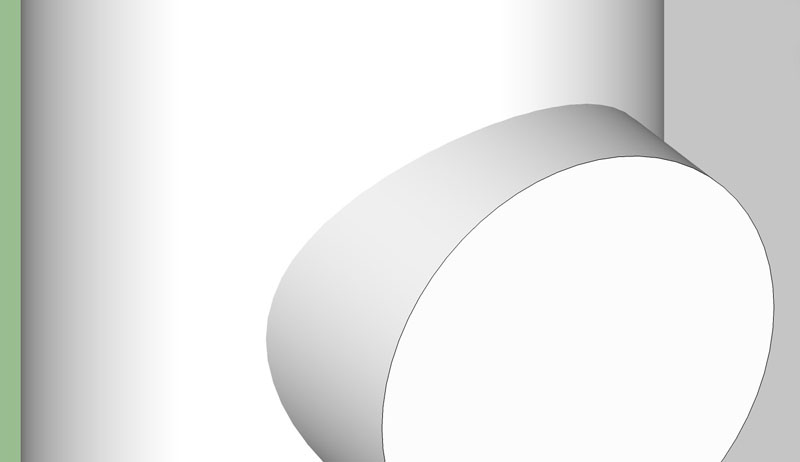
Here's the mesh after intersection. You'll notice some smoothing issues now which are the primary issue.
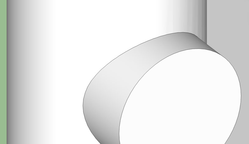
Here's the reason. The cylinders intersection breaks up the triangulation since each of the segments intersects in between other segments. I've tried manually adjusting this but then the small cylinder doesn't end up with enough segments to appear correctly.
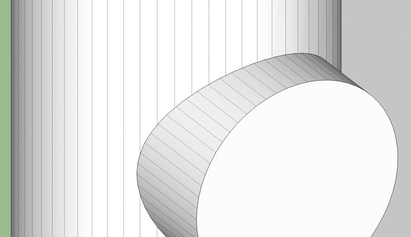
How would you resolve this issue? I've tried skirting it but I can't seem to make it work. Any thoughts?
-Brodie
-
Here's an example where both cylinders have matching segments...
Do you want a Surface blend between each cylinder?
-
That's pretty good. What did you use to get that result?
There are a couple things going on but I was trying to solve this issue first. The other two issues are getting the sort of bevel where the metal wraps into receive the small cylinder and getting that sort of surface blending that looks like it may be a weld spot or something. I'm open to ideas on those issues as well.
-Brodie
-
@unknownuser said:
The other two issues are getting the sort of bevel where the metal wraps into receive the small cylinder and getting that sort of surface blending that looks like it may be a weld spot or something.
Forgive me if I'm not quite understanding you correctly but wouldn't some follow-me get the job done?
-
That's certainly where I'll start. I did one small test, however and didn't get great results. With the number of segments I have when I ran the follow me the segments of the bevel sort of overlapped on eachother and caused issues. I'll still have the issue of combining that with the 'weld' spot as well. If I could somehow do the weld and the bevel in one go it seems like the mesh may be cleaner but I'm not sure how I'll do that.
-Brodie
-
Here's one with a surface blend....
Use Circle on Surface in the Tools On Surface plugin. Delete the face then use TIG's EEbyVector to extrude that 'Ring'.
You'll have to scale this to get it circular afterwards though. I should screen capture this but my Java's acting up!
Thought you had 3DS Max? It would be a snap in that.
-
I noticed the same problem too. In general I add redundant soft/smooth edges to reduce the significance and help triangulation.
Ogan
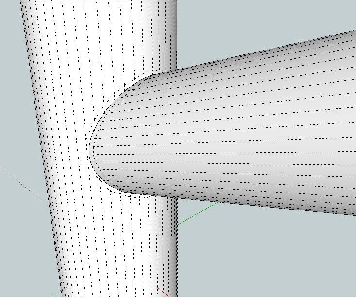
-
2 things on the last model. The bevel is going the wrong way but that is a great idea for getting the bevel. I incorporated it in the image below. Also the shading issues are back in the model you produced. What did you use to subdivide the first model you provided? That seemed to do a good job of smoothing the shading.
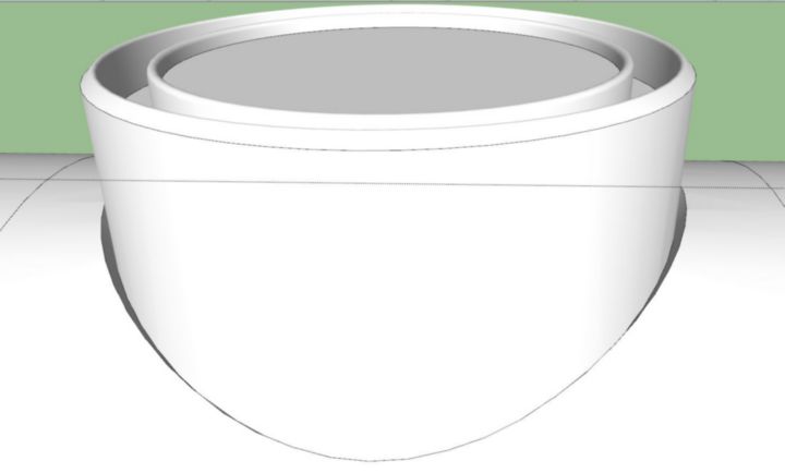
Your idea also gave me this idea which greatly limits the problem shading area. Curviloft from the smooth cylinder to the jagged cut and then curviloft from the jagged cut to the bottom of the bevel.
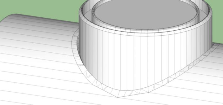
Still not a great mesh and although the area is limited it still has smoothing issues.
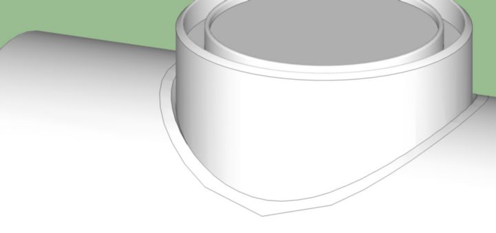
I do have 3ds Max but I suck at modeling with it. That's probably my next stop though. I'm pretty much there in SU but I'd really like to have no smoothing issues AND a clean mesh which isn't looking all that likely. I'll see what Max can do.
-Brodie
-
Tools on surface and the scale tool will do the trick.
I will try to post an example soon. -
Fredo's Create Loft by Junction has many spline methods to tweak the surface blend. But to be honest you'll struggle in SU to get the optimum result. Rhino/MOI etc do this is seconds though. My 3DS Max trial ended weeks ago some I can't try it in there.
Here's some blend variants...
-
Rich, sorry, I don't think I was clear. What I was referring to wasn't the surface blending but the very first model you sent which wasn't blended at all but it had an interesting subdivision to it. I didn't know if you'd used a plugin to create that or done it by hand.
-Brodie
-
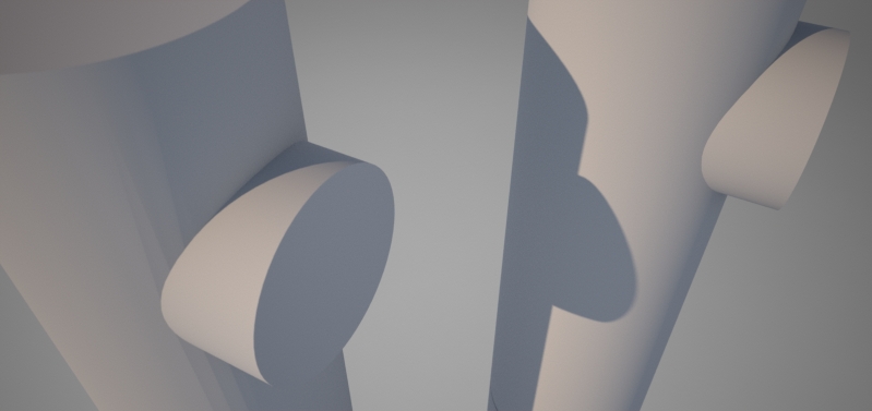
Oh ya, and just to illustrate my shading issue I'll show you a quick maxwell render. Notice how the shading issues in SU translate to shading issues in Maxwell. The one on the left is after intersecting the cylinders, the one on the right is before intersecting them.
-Brodie
-
Sorry, I see what you mean now. I did it in MOI as intersect in SU doesn't triangulate the mesh. MOI has a great .skp export option the help control the polys and keeps surfaces smooth.
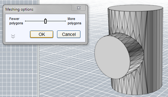
But why do you need them to intersect? Did you try rendering them as separate components but occupying the same space?
-
Well, normally I'd do that and not worry about this mess but, as I said, I'm hoping for a highly detailed model this time for some closeups (and as a modeling exercise) which means it needs a cutout which bevels back leaving a bit of a gap between the larger cylinder and where the smaller cylinder fits into it.
Hrm, don't have Moi but maybe Max has something similar I can find. I did a quick test with Max and god the same shading issues but maybe there's another tool in Max to do this better.
-Brodie
-
Brodie, here is a modeling example.
[flash=853,505:3bdh7ugj]http://www.youtube.com/v/G__mig97om0&fs=1[/flash:3bdh7ugj]
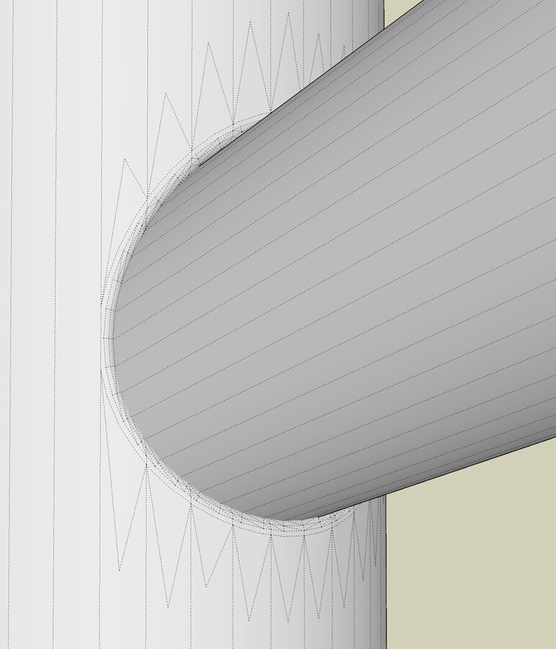
After doing the video I read more about your shading issue. If you stitch some simple triangles around the opening they seem to disappear. I did this in Twilight with a porcelain texture.
Hope this helps.
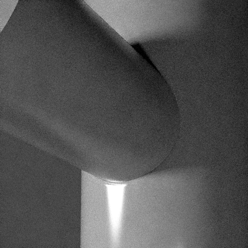
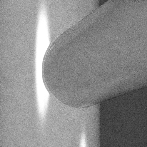
-
Oh man I had the whole blend reversed.

No wonder I was confusing things. I'll have another play with this.
Look for Blend Surface in Max though it'd be faster. I know Max has a tool for this as standard.
-
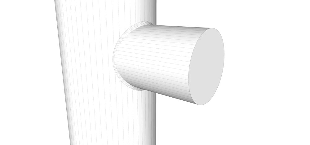
Pretty simple using TOS, EEby Vector and follow me.
-
Your bevel is in the wrong direction Pete.
-
Solo,
You cheated
 The blend is going the wrong way in your image so it would require no intersection which is what causes the shading issue. If you notice in the original image the metal doesn't really come OUT to meet the small cylinder, it's just bent IN(other than what I'm calling the "spot weld').
If you intersect your objects and smooth it out you'll see the smoothing issues I was having.
Boo,
Very interesting method. I quite like that it keeps the mesh very clean. Even your solution for fixing the smoothing issues isn't too destructive to the mesh. I'll take a crack at that.
-Brodie
-
@unknownuser said:
Your bevel is in the wrong direction Pete.
I guess I need to read the first post, I was wondering what all the fuss was about, looked like a simple elementary modeling issue.
Advertisement


