Please help... :S ( British Museum roof structure )
-
I have tried to make British Museum roof structure. I learned how to make the basic geometric shape on here but the circle and square mixed roof is too difficult to make.
-
Hi,
Found this in my bookmarks folder - might give you an idea of accomplishing that with SDS ( Artisan)
http://www.bath.ac.uk/ace/subdivision-surfaces/ -
Hi Numbthumb,
Thank you for your reply. It's really good site. I saw them too and it helped me to understand the principle but still in trouble to make them. I didn't read them all so I'd better read them all first. Hope it gave me an answer suddenly

-
As long as you only want something 'like' the BM roof then you can use EEbyRails to get the mesh [or one of several similar tools], and with hidden geometry 'on' toy can also adjust the mesh's vertices etc as/if desired... and then use LatticeMaker on the mesh's faces to add the frames/glass; or try EEbyLattice directly; or make the mesh with EEbyRails etc then using the same profile/rail curves use EEbyLattice to make just the rib lines, then draw a flat face representing the cross-section for the glazing bars [with a guide-point to set its origin if not centered] and use that in EEbyFace to add the glazing bar profile to one set of ribs, rotate the face and use it again on the other set of ribs. You need to do some judicious exploding of the grouped parts at different stages and some use of 'intersect' to get lines at face intersections etc BUT this way you can customize a meshed surface glazed roof with non-rectangular glazing-frames etc...
-
There is a tutorial here by Simon Le Bon

(scroll the page) -
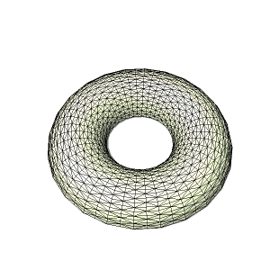
Here's another way. This is using the subdivide function of SDS, but if you don't have it you could always manually triangulate a small section then perform a circular array.
This was just a quicky. It's obvious that if you have about twice as many segments in the circular path, you'll get squarer facets rather than the long rectangular ones.
-
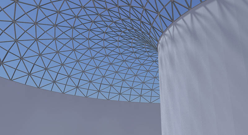
I got this result by using a circle with 18 segments and a circular path with 36, then used Subdivide and Smooth...which doubles the numbers as well as triangulating. I then cut off the bottom half and deleted everything except for a two segment wide strip running from the exterior to the interior. This was obviously 1/36th of the entire circumference...10°.
I then used the Offset tool and PushPull on this small segment (boring, but only about 5 minutes work) before making it a component and arraying 35 copies.
-
@Alan It looks nice, but if the goal is to model the British Museum roof it doesn't quite cut it?
The main problem is that it should be a (slightly flattened?) "hemi-thorus" with rectangular footprint/perimeter and circular hole. Besides, there are no horizontal ribs in the BM roof.
Another question (I've not been able to find a big picture of the outside) is whether all glass panels are the same size? Could they possibly be?
It is a real tricky modeling project indeed!! -
Meh! Details, details.

Circular to rectangular; no horizontals. Done without a single plugin being used.
You are right about the lack of decent exterior pictures. It makes it very difficult to analyse the structure; and all the interior shots have very misleading perspective...plus of course you can only see a small fragment.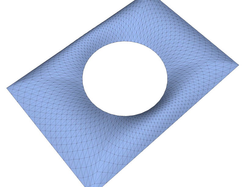
The clue lies in this shot.
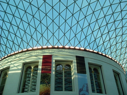
See the way every other rib never quite makes it to the centre? In the SU mindset, that's because they used to be concentric horizontals...every one of which has been flipped the other way. So that's the way you construct it in SU...then flip them. My attempt has exactly the same feature/
-
Nice again

I just found a top view of it, from a WIP that claims that it was drawn from a plan in a book.
http://forums.cgarchitect.com/36383-british-museum-great-court.htmlThe even, swirly vertical ribs would be quite difficult to make without a lot of hand editing, don't you think?
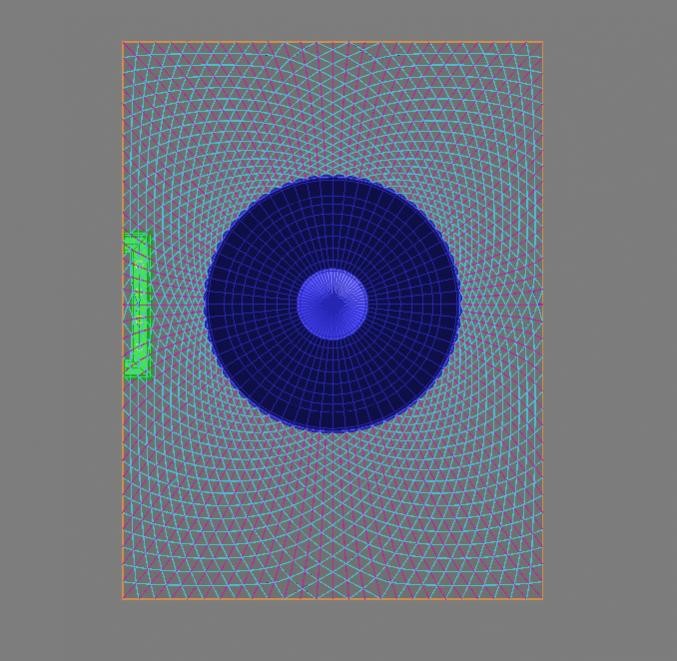
-
@bjornkn said:
The even, swirly vertical ribs would be quite difficult to make without a lot of hand editing, don't you think?
Absolutely. I don't think it's possible to take shortcuts with this. I found that it's even important which diagonal you draw first when triangulating the 'squares'. If you do the wrong one, then those swirly ribs get distorted.
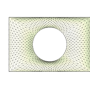
This needs a little more refinement, but here is the basic methodology:Lay out a groundplan.
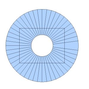
Intersected and stretched a little more rectangular.
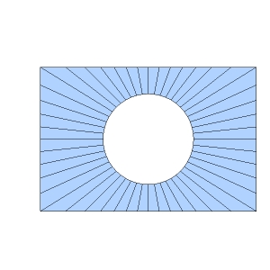
You only need 1/4
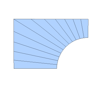
Pull every other segment upwards.
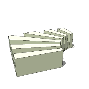
Delete the joining lines to leave the vertical planes.
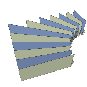
Construct curves on each face...equal segments, equal height.
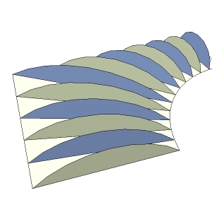
Skin and triangulate...a full X in each square section, not just the single necessary diagonal
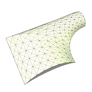
Flip all of the horizontals to create intermediate radial ribs.
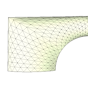
Mirror copy to complete.
-
This is from the 80 megapixel panorama of London

-
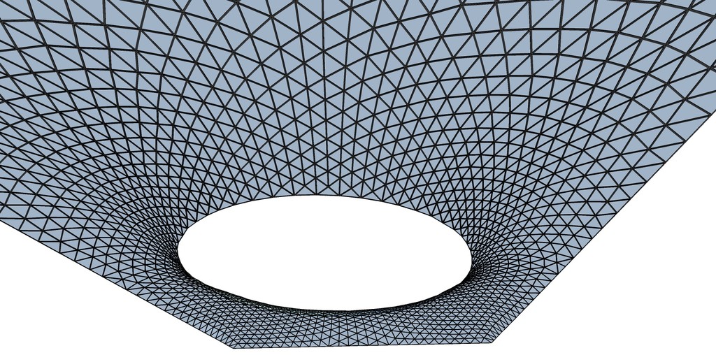
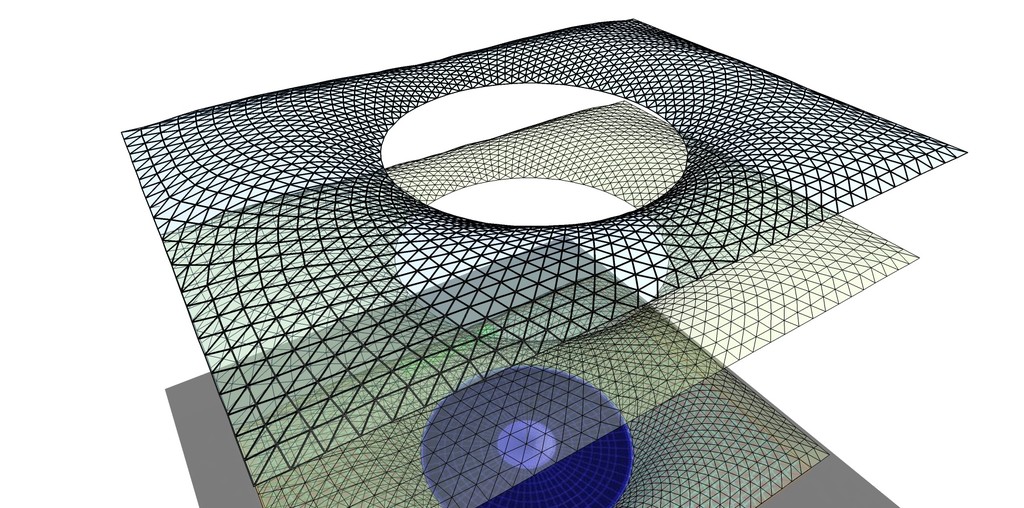
Here is my go at it. I love a challenge, and hate to give up

It was lots of work, and quite a lot of hand editing.
Without Amorph Bezier curves and view locking I don't think I would have tried.
It could still need some tweaking, and I just noticed that the rotunda is not in the middle of the room on the plan !
Used TIG's LatticeMaker to make the frames/glass - it took almost 2 hours in all!
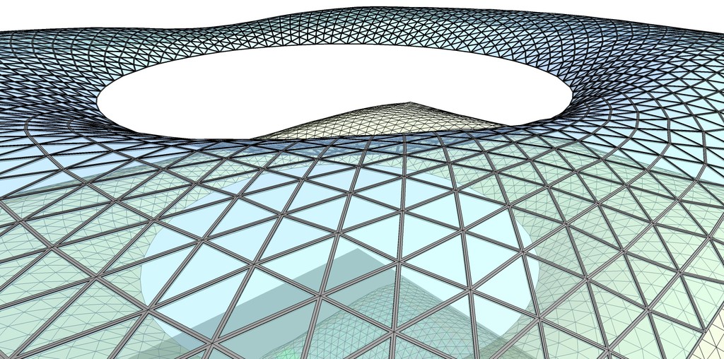
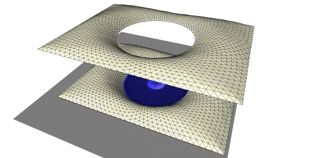
-
Alan, I'm trying to follow your methodology and got lost at the "skin and triangulate" and "flip all the horizontals". What steps did you take to "skin and triangulate"? Did you use the skin.rb and sds? The second question is what do you mean by "flip all the horizontals"? I see the horizontals are gone but how are they flipped to accomplish what I'm seeing. Thanks for any insight.
-
OMG!!!! You guys are GENIUS!!!!! I didn't read all yet but there is the answer for sure! Thank you sooooo mush!
-
I have to warn you that my model is not entirely accurate, as the actual roof does not have straight radial ribs, they are slightly curved; nor does it have obvious diagonals at the corners...nor is it the same height along the narrow sides that it is along the broader ones...nor is the central, circular reading room exactly in the middle (as Bjorn points out). There are also about 50% more segments going outwards on the broader side than on the narrow one...and about 100% more on the diagonal. Otherwise it's fine.

I found a clearer layout of the rib structure. Apparently the first drafts were mathematically procedural...rather like mine, but left awkward shapes around the exterior. The final result was arrived at after much experimentation and represents a compromise between visual appeal and stress considerations. (The whole of the circular edge is on 'castors' to avoid any lateral strain on the Reading Room. The accuracy is phenomenal. It's over 90m long yet is accurate to +/- 3mm.
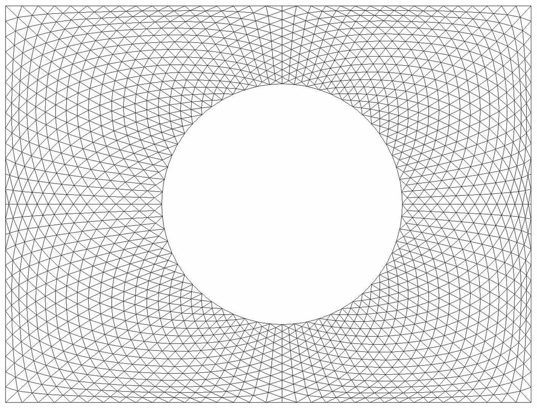
I used the Curviloft skinning tool, but to be honest, it wouldn't have taken much longer not to...because many of the produced diagonals were the 'wrong' ones. I also forgot to mention (but it's fairly obvious) that I first deleted the base lines of all the arcs...so that you're left with just a framework of edges to deal with.
I think I mentioned somewhere that it was important to decide which diagonal went in first. By diagonals I mean those that fill-in the roughly square shapes defined by the horizontal lines.. Because these shapes aren't planar, you can't simply draw two diagonals. You have to draw one, then draw the second one from the corner to the mid point of the first diagonal...then to the other corner. If this second diagonal is something of a dog leg, then erase and do it all the other way around.By flipping, I simply mean use the Flip tool in the Sandbox to turn all the horizontals into radials.
I hope you can follow this.Bjorn, really great job. I had another go myself after I found more accurate reference. This is definitely something that can't be automated....although I have seen an animated demo done in Rhino. I think it may be on YouTube.
-

[flash=425,349:kwxv0ccf]http://www.youtube.com/v/-AGQajhDegM?version=3[/flash:kwxv0ccf] -
Nice video

Any idea why YouTube videos can't be viewed at full screen on this forum?Thanks to Alans new and better plan I had to waste some more time on this

Here's a short tut of the first steps of making it with Amorph.
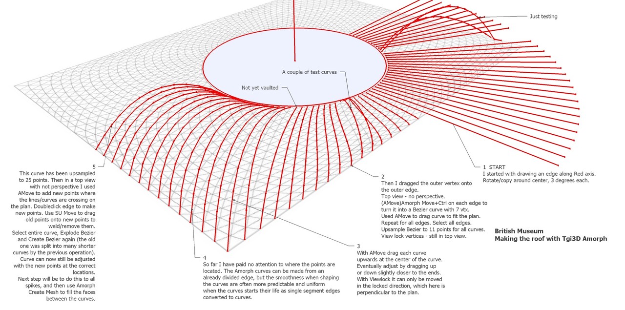
-
@bjornkn said:
Any idea why YouTube videos can't be viewed at full screen on this forum?
The way YT videos are embedded nowadays have changed and the forum software only allows the old embed code which is now limited.
-
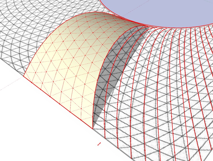
Here's a little update on the roof, with a few curves finalized and filled in with Bezier meshes. It is actually a lot faster doing it than describing how it's done..
Advertisement


