How to import a PowerPoint slide?
-
I see. thanks for that explanation. What about the 2D/3D question?
One option you might try for the text is to use 3D Text (without extrusion if you want it flat). It comes into the model as a component which would have several benefits in this case. One is that the components can be saved into a library for later use. The other is that the component's axes and thus it's insertion point can be placed as needed. You could use ThomThom's Axes Tools to move the insertion point so that you can drop the text onto the blocks or wherever you want them and have them centered. As far as that goes you could do the same thing with the blocks if you wanted. If you have a limited number of named blocks you could just build all of them in advance and then drop them to a grid of guidelines.
I've done a similar thing for clock face numbers and in that case, I quickly drop the numbers onto the vertices of a 12-sided circle centered on the face.
As to the lines in your 3D view, you may have figured out that you could hide the edges on the blocks without hiding the other lines.
-
Thank Dave R for many good points which I will have to study carefully.
@unknownuser said:
What about the 2D/3D question?
I wanted to point out that limiting myself to a 2D scenario would diminish a number of alternatives, which would make the solution less valid for a number of situations. - The tool should generate one set of diagrams which can quickly be adapted in many ways according to the customer's aspirations and taste.
I tried to use '3D Text' and without extrusion. That would be very powerful indeed. Unfortunately I couldn't find a way of excluding text elements from style transformations and so the text turned often out to be quite unreadable. Maybe your advice contains some hints to resolve this problem. Otherwise I will have to find out how TIG created his 2D Text objects.
-
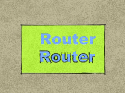
Actually, with what I wrote before, 3D Text elements would indeed be affected by the application of style settings in SU. There is a simple way around that, however. Make a separate layer for the 3D text. Put the rest of your components on another layer. Make two scenes with the camera in the same position. One will show the just the text with no style applied. The other scene would have the blocks and connecting lines visible but not the text and in that scene, you would apply your sketchy style. Export both images and then combine them in an image editor. Paste the text image onto a layer set to Multiply in the editor.
Although not exactly the same as what you're after, I did this a little bit ago in preparation for a tutorial I'm writing on something else.
I made three image exports.
First, a textured view with no lines.

Third, lines only with a sketchy style I made.

I combined the images in my image editor and got this.

Actually there were a few additional steps for this image. I edited the shadow image to blur it a little. I combined it with the faces image, ran that through FotoSketcher and then combined that result with the sketchy lines. In your case, replace my sketchy lines with your 3D Text image. And the faces image with your image of the blocks and lines. If you don't do any of the extra stuff, combining the images will take less than a minute.
-
My 2Dtext has its edges hidden - so unless you use a Style showing hidden-geometry the 'flat' 3d-text that's used in 2Dtext shows as a set of unedged faces [colored as you specified] - it's unaffected my most types of Style settings - so it's consistent, unless you are viewing in Wireframe, B&W or Monochrome model in which case you either won't see the text, it'll be white or it'll be in the default-front-face color [usually off-white]. The 2Dtext components also don't receive or cast shadows, and are set ~2mm above the surface they snapped to to avoid z-fighting... Clearly 'blodgy' coloring Styles will affect the text but you'd probably want that, as otherwise it'd look like an 'overlay' of separate text = like you'd get from exporting a separate styled text-only layer ??
-
You can hide some edges without affecting others. Either select just the edges you want to hide or run over the edges with the Eraser tool while holding the Shift key down.
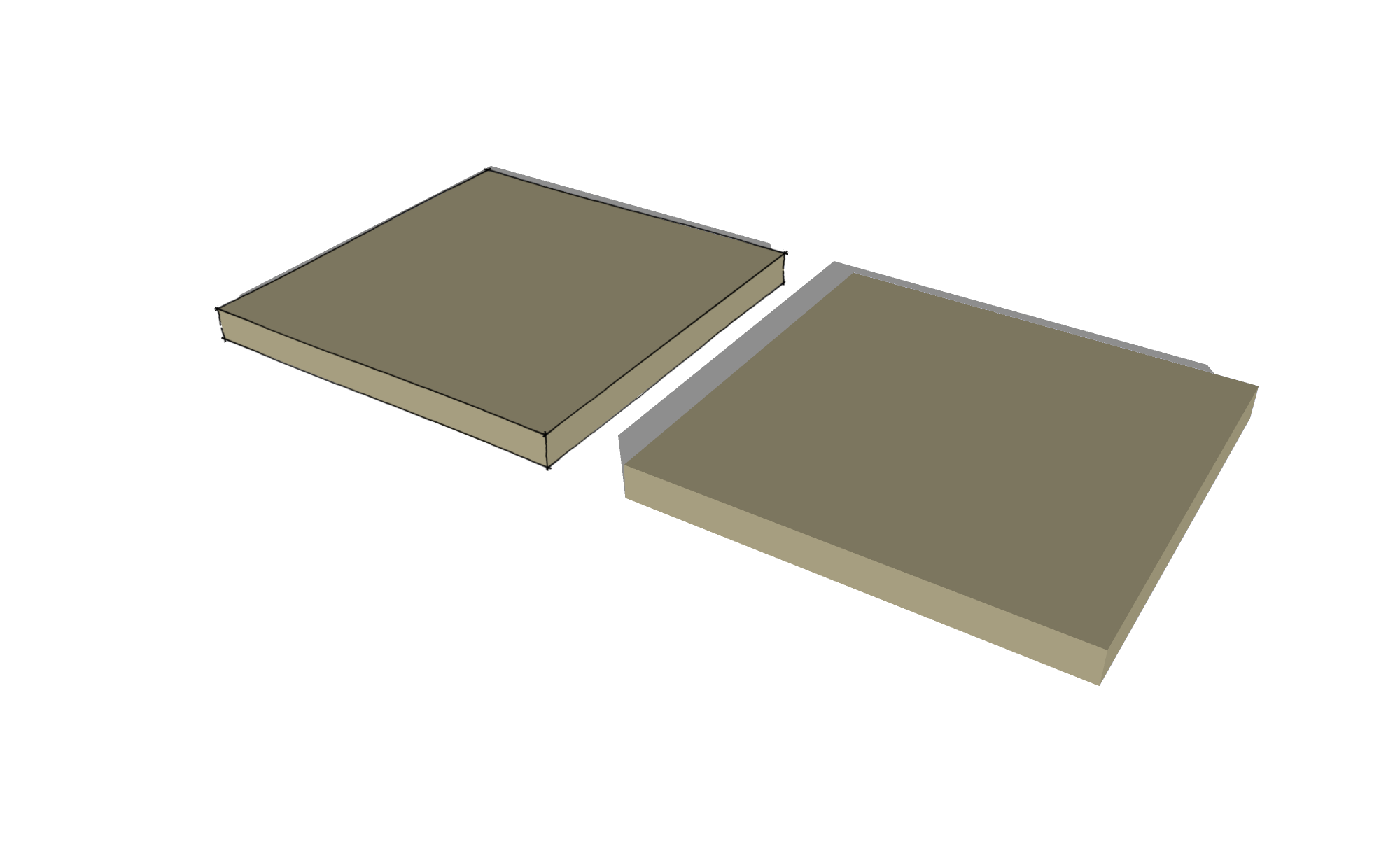
Here's a quick example. I hid the edges of the box on the right and applied a sketchy line style.

-
I think I understood what Dave proposed: Combine styles with scenes and export the scenes to a bitmap tool which can handle layers. Seems to work, but it brings in yet another (third) tool where you can combine the layers.
But TIG suggests that we should create everything directly in SU by hiding edges of the text:
@unknownuser said:
My 2Dtext has its edges hidden - so unless you use a Style showing hidden-geometry the 'flat' 3d-text that's used in 2Dtext shows as a set of unedged faces [colored as you specified]
- 3D Text: not extruded, colored, no edges
Is there a way of doing this in the GUI without affecting all entities. Can we hide edges of one object without affecting the other ones?
-
Stupid me. I should have been able to figure out this trivial matter by myself. This is why I'm insisting on posting on the Newbie forum. Because there is so much to learn before I cease being a newbie.

Dave's demonstration also explained why the lines were hidden away in the 3D rendered model. Because lines are being hidden at the same time as the edges. - I guess I'm through now with all conversion problems or am I?The next task of generating a PPT slide in a SU window should perhaps be discussed in a Ruby (newbie) thread and not here in the Newbie forum.
-
@pdonner said:
...Because lines are being hidden at the same time as the edges.
Keep in mind that some rendering applications don't show edges (lines) from SketchUp. They are shooting for realistic looking 3D stuff so lines by themselves won't be shown. If you are planning to do something other than just image exports direct from SU, you might have to find a way to deal with the lines.
-
To quickly hide all edges in a group/component (like how 3D text comes in), you can follow these steps:
- Edit the group (double click)
- Turn your face style (View menu) to wireframe
- Select all (Ctrl+A)
- Hide (Edit menu or roght click...)
- Turn shaded (with textures) back on and exit the group/component
If you want to "spice up" your 3D presentation, you can even embed some 3D views of your objects with Hypercosm (there is a free version of the teleporter, too). Here is how to embed a hypercosm applet in PP. You will need the Applet from the download page above (on the right) in order to get it to work.
PP 2000-2006: http://www.hypercosm.com/support/howto7.html
PP 2007: http://www.hypercosm.com/support/howto8.html
Note that if you are planning to run it on any other computer than on what you are making the presentation, all files need to be in the same place (and the applet installed). Best if you make a folder, put your ppt file in there and add all the necessary hyperosm files, too then move that whole folder with you.
Once an IT guy screwed up a presentation of mine. I told him to do the above but he thought he was smarter than that.

-
Gaius' #1-5 recipee brought the topic back to newbie level. Yes. Wireframe is the correct procedure to choose all edges and then hide them. Something that I didn't think of. Deselecting every face of the 3D letters manually can be tiresome. But I guess that TIG does this with one or two lines in his Ruby script.
-
Well, I suppose in a plugin you can easily do things that are just over and beyond us, puny humans...
Advertisement


