[Plugin] Dxf_In v2.2 20110517 Dxf2Skp
-
Here is the attachment. Thanks for the tips. I left the file at work, so couldn't send last night. Sounds like we can do dxf's now.
-
Looking at the Blender dxf importer (written in Python) and found these dxf test files in the Downloads section:
-
V1.2 provides the option to select input units, and location (thanks to_tt). Not being familiar with metric conversion, I did not check their accuracy.
 Btw: In regards to lwpolylines, when I wrote this translator, I found that the dxf example I used contained occasional differences in the actual number of vertices's, and the number provided by the dxf. So, I ended up writing a procedure that did not depend on the stated number. I am not sure if this is a misunderstanding on my part or a bug in the program that created the dxf.
 -
Sigh...As soon as you think you got it, there is something to change, hence v1.1. Functionally no different, but with better error messages. Unless I find a bug, or figure how to add a polyface mesh, this should be it:-) Attached are some test with old.dxf models.


The model's groups are based on common materials, textures, or colors. This makes it is easy to update the SU model's textures of any Cad based revision. The groups/blocks are sent both ways so that the production drawings are easily revised based on changes to the model. -
@honoluludesktop said:
Btw: In regards to lwpolylines, when I wrote this translator, I found that the dxf example I used contained occasional differences in the actual number of vertices's, and the number provided by the dxf. So, I ended up writing a procedure that did not depend on the stated number. I am not sure if this is a misunderstanding on my part or a bug in the program that created the dxf.
I can't find the reference now, but I understood it to say something similar to "polylines that can be converted to lwpolylines, are converted into lwpolylines in order to save space."
I have a routine to handle the bulge data for regular polylines, but the lwpolylines are different enough that I haven't been able to decipher them consistently.
I found a dwg/dxf converter for Windows that may be of interest. It converts between dwg and dxf, but also from dxf to dxf and you can choose several versions of the file format. So maybe it will be useful for converting tricky dxf files into older formats which your importer is more tolerant of.
The converter is here, under the name ODA Teigha File Converter.
-
Jim, I am using Dxf Reference, ACAD 2010 and am not able to identify bulge data within dxf polyline.
The group code for bulge in lwpolyline "42", is absent in the 2010 reference for polyline unless it is part of "70" and some other group code. I don't look forward to figuring out how to including it in Dxf_In.Incidentally, Dxf_In doesn't check for version number, and will attempt to process any File.Dxf, even one that is manually, incorrectly edited, and rejected by Import SU Pro. It has succeed for the implemented entities, except when the group code is written out of order. I noticed that import SU Pro V7 refused to translate a 2010 Dxf file.
-
Hi Jim, Thanks, I have used that open source translator from time to time, especially with a cad.dxf that needed to be accessed by older programs. It has a difficult interface requiring two folders, one for the file and the other for the export. As I recall (perhaps erroneously) it did not allow you to select specific files for translation, and processed the entire folder.
When Dxf_In detects a lwpolyline, it process it as a SU "continuous edge" by assuming z=0.0. I am not sure if that's what's intended for that entity type, but have successfully translated the examples I had access to at that time.
There were other anomalies I noticed in comparing Dxf_In to SU Pro imports. The windows in the energy model above, imported with SU Pro, are faces in the same plane as the wall (surface) they are on. Hence the problem displaying its color. For some reason, Dxf_In corrects this by drawing the window as a faced hole in the wall. However, Dxf_In draws some of the energy models faces, back side out, where SU Pro draws them properly. I speculated that the cause of this maybe in part, the order that the faces are drawn. Dxf_In, processes the Cad.dxf in the order the entities are listed. Perhaps SU Pro pre-processes the entities before drawing them. Btw, I hadn't realized that polylines have "bulge". Although I haven't encounter any that did, I guess I need to look at that entity attribute. Is my post above regarding bulge calculation correct to your understanding? Also puzzling to me were the entities in some dxf files that by the manner of their identification in the file, are not drawn. If file size is a consideration, I wondered why these were included in the dxf file.
-
@honoluludesktop said:
Jim, I am using Dxf Reference, ACAD 2010 and am not able to identify bulge data within dxf polyline.
It's the POLYLINE's VERTEX that may or may not have a bulge attribute. POLYLINE's are implemented as a sequence of VERTEX's, ending with a SEQEND code. LWPOLYLINE's can have multiple vertex and bulge data but these are stored in the object itself as multiple 10, 20, and 42 codes.
@honoluludesktop said:
Incidentally, Dxf_In doesn't check for version number, and will attempt to process any File.Dxf, even one that is manually, incorrectly edited, and rejected by Import SU Pro. It has succeed for the implemented entities, except when the group code is written out of order. I noticed that import SU Pro V7 refused to translate a 2010 Dxf file.
I am in the process of separating out the dxf reader part of my importer to be more generally useful. It reads a dxf and converts it into a Ruby data structure of Arrays and Hashes. This will allow access to the sections and entities much easier.
Header variables:
dxf = DxfReader.load("c:\drawing.dxf") acad_version = dxf['HEADER']['$ACADVER']Iterating ENTITIES:
dxf['ENTITIES'].each do |entitiy| process_entity(entity) endViewing a specific, or entities by type:
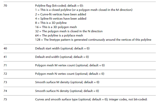
all_lwpolylines = dxf['ENTITIES'].select{|e| e[0] == 'LWPOLYLINE'}In addition, you can "pretty print" the dxf allowing for easier analysis, such as this image of the representation of a LWPOLYLINE as a Ruby data structure.
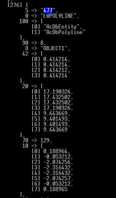
You can see the lwpolyline has 8 vertices (code 90), but only 4 of those bulge data (code 42). I know how to create an arc from 2 verts and a bulge, but I don't know how to apply that formula to this particular lwpolyline.
But with the DxfReader, you can pick out and try to create this one particular entity for debugging:
lwpoly = dxf['ENTITIES'].select{|entity| entity[5]=="477"}.first x_values = lwpoly[10] y_values = lwpoly[20] bulge_data = lwpoly[42] nverts = lwpoly[90] for i in 0..nverts-1 pt = Geom::Point3d.new(x_values[i], y_values[i]) entities.add_cpoint(pt) end
(etc.)I will try to clean-up and post the reader this week.
-
Jim, I think I get it about bulge in polyline as "a sequence of vertexes". The dxf reader sounds like a great tool. Just an idea, but perhaps in addition to displaying the group code, you could provide a short meaning of it (probably too much work).
In the process of material importing, I tried to convert Acad's basic colors to the ones recognized by SU. Wow, too much work for me, and there were to many approximate correlations. Then I thought of setting the RGB values in SU, but that wouldn't cover materials, so I decided to leave it in the hands of the user to make sure that the same material existed on both sides. Because I do not use ACad, I can't test the validity of that assumption, and will have to depend on feedback. Now I see this discussion, and will leave the matter to experts.
I read that lwpolyline was implemented by ACad in version 14. So unlike my original speculation, it is not an old form of polyline, rather a newer one then polyline. To my understanding, It is a 2d, variable width, entity that supports curves between pairs of vertex. One application is as "arrow heads" at the ends of dimension line. I have yet to read an explanation why this entity was created. Perhaps because, it helps reduce the size of the drawing database, especially with those that are primarily used in "production drawings".
-
V1.5 adds layer names, and materials to faces. In addition, the initial user interface is now organized as a single options menu.
When selecting DXF_In materials on, unless the material exists in SU, the resulting face is black. I currently have not thought of a practical way to handle that situation.
Jim, I have been reading up on lwpolyline, and polyline entities. Thanks for your post.
-
Oops...wrong conversion values for metric scales. Corrected with v1.6. In addition to minor adjustments, "check for upgrade" is a selection from the Option menu. "Yes" to this will take you to the top of this topic, and clear the options returning SU to its previous condition.
-
V1.9 includes improved user interface, and support for faces by layers and materials. The default material colors are based on Acad's color chart of 256 colors. Unlikely to be used, but included is support for colors by SU's color name chart of 140 colors, and the current model's colors. Btw, I had to manually reverse the faces on the right side, near wing of the model.

-
Thank you very much!!!!
-
V1.10 places a rescaled dxf model on the mouse pointer.

The import file name is in the upper left. Check update take you to the top of this topic's page, and import units include metric as well as imperial scales. Import origins are placed on SU's origin, or subject to the mouse pointer. The default import is for closed polylines to faces, however this may be turned off. Dxf colors by Acad number is also the default, SU names, SU's model materials, or none may be selected.I think all the interface issues have been addressed. I do not intend to add other entities (perhaps only as requested).
-
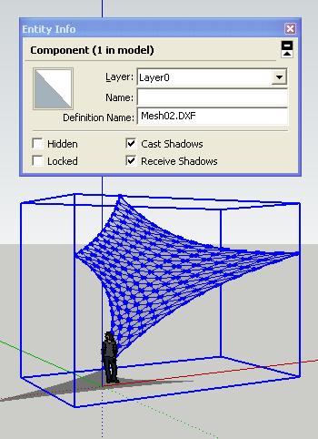
V 1.14 includes minor interface refinements, and the "help option" to save current option selections. Below is a example of an imported 3d polymesh whose definition name is created from the name of the file.dxf.
-
Honoluludesktop,
How do I get a copy of your DXF importer plugin? It looks like just the thing I need.
Thanks,
Jim B -
It's here at the top of this topic.
-
honoluludesktop
great work!
imported 3d polymesh from construction software(agtek)generated dxf
the terrain looks perfect...
-
Thank you for this plugin, very useful.
-
Added Dxf_In v1.15 french translation thanks to D. Bur.
LES ENTITES DXF SUPPORTEES SONT:
- Polylignes comme arêtes connectées.
- Polyligne's (fermées) comme faces sélectionnées par l'utilisateur.
- LWPolylignes comme arêtes connectées.
- Lignes comme arêtes.
- Cercles comme contour d'arêtes.
- Arcs comme contour d'arêtes.
- 3dFaces comme faces.
- Blocs comme groupes ou composants.
- Maillage Polyligne comme arêtes.
- Maillage comme faces sélectionnées.


Hello! It looks like you're interested in this conversation, but you don't have an account yet.
Getting fed up of having to scroll through the same posts each visit? When you register for an account, you'll always come back to exactly where you were before, and choose to be notified of new replies (either via email, or push notification). You'll also be able to save bookmarks and upvote posts to show your appreciation to other community members.
With your input, this post could be even better 💗
Register Login


Advertisement