Help with Rafters
-
I have come along way on this model. I know it is not perfect but for a first attempt, I will take it. The main purpose of creating this model is to sell the idea to my wife and get some bids from potential builders.
The last things that I need to do are to put on the roof and decorate with some furniture. I am at a loss as to how to add the roof. I have not heard from Tig, (who has been extremely helpful), in a few days so have to assume that he is busy helping some one else. If anyone can tell me how to make the roof, I would really appreciate it.
As for the furniture, I have scoured the Warehouse and not found any suitable outdoor furniture. Are there any other sources for components where I might find these items?
As always, I really appreciate all the help.
Bob
-
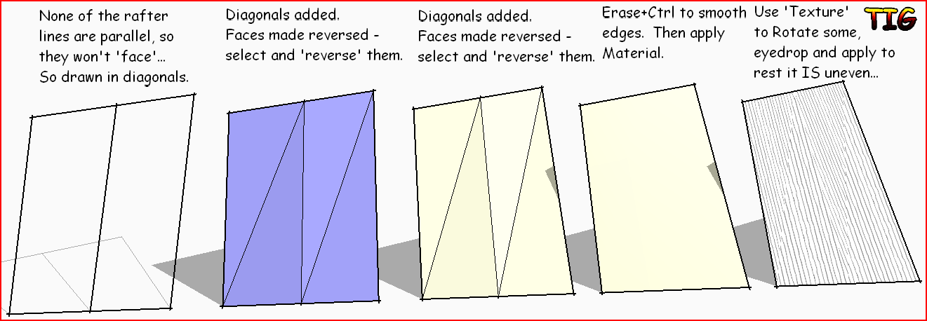
Try this way...
-
dsafety
Yes you can put a zero thickness skin on that way to form a warped surface. I think each non zero thickness panel may have a compound miter cuts and make sure you ask the contractor about the details of his bid so you don't find your self in the situation of them claiming later that type of work is out of scope !! BTW I think each rafter is the same case. Also make sure you and the contractor understand what the code requirements are if any and that is factored into the cost. Many years ago I was a city inspector and a recent roofing contractor tried to play that game with me. Believe me they will in many cases unless you get all the understanding up front and written down. Attached is a rough idea of what your roof profile will look like
No reafters, soapa kin and bubble plugin ref the eaves and ridge beam edges
-
Thanks Mac1. Your solution appears to be flat while using Tig's method I ended up with several facits. How did you come up with your rendering?
Bob
-
@dsafety said:
Thanks Mac1. Your solution appears to be flat while using Tig's method I ended up with several facits. How did you come up with your rendering?
My approach is not a rendering and as noted was meant to show you just a rough idea what your roof will look like. What I did was use the ridge and eave beam edges as a ref ( rafters follow that profile) connected at each end with a line one to the other then used the plugin Soap Skin and Bubble to create the surface. This is not acceptable for your final model. Using the first and last rafters could also be tried but have not looked at that. TIG's approach will work but it would take many facets ( maybe as many as 50 etc) for each space between the rafters. The reason is the double curved surface. Fredo's curviloft will do that work automatically and does not look bad. As I have been harping about I think you should reconsider your approach unless you want that type of double curved surface and are willing to spend the bucks. There is a solution which keeps the splayed beams and will result in a flat roof but I stopped working on that approach based on your previous comments about the OP approach was good enough. Attached is where I stopped. You can finish if you want. The concept is the splayed beams are raised in the back bringing their edges in plane with the center. The beams were corrected and made components because of the varying dimensions. A slope reference( 17.589 degs but needs verification) was measured then moved up by 6/cos( 17.589) to account for the rafter plum cut ( should have used 2x4) was made at the front and then copied to the back to establish how much the splayed beam must be raised. From there is it just a matter of laying in the rafters. You can trim the roof line by using a section plane. Note the clipped corner needs correction
Good Luck
Bob
-
Thanks again Mac1. I think I understand and agree that having a flat roof would be much easier to build and probably cost a lot less. If I raise the center post furthest from the fireplace, (or lower the hight of the post at the fireplace) to the point where the roof will all be on one plane, it should work out. I do not know how to do the math to figure out how much to raise or lower these posts. Could I use guidelines instead?
Bob
-
@dsafety said:
Thanks again Mac1. I think I understand and agree that having a flat roof would be much easier to build and probably cost a lot less. If I raise the center post furthest from the fireplace, (or lower the hight of the post at the fireplace) to the point where the roof will all be on one plane, it should work out. I do not know how to do the math to figure out how much to raise or lower these posts. Could I use guidelines instead?
Bob
Take a look at the ref triangle I have drawn in the above post. The one point(A) of that at the top outside beam edge is the start of the birds mouth. The other is on the line at the plum cut(B) at the top beam. If you now take and move/copy the triangle down to the far end and set the one point(A) on to the out side beam edge the triangle will cut at the ratio you are looking for to keep the same slope. Opps I noticed I went high in my last post vs low
 Since you think this is a possible solution I'll see if I can do some more tomorrow ( PM it will be)
 -
-
-
Thanks Mac, I have encorporated your roof into my model. It will be much easier to build. I will post a finished model soon.
Bob
Hello! It looks like you're interested in this conversation, but you don't have an account yet.
Getting fed up of having to scroll through the same posts each visit? When you register for an account, you'll always come back to exactly where you were before, and choose to be notified of new replies (either via email, or push notification). You'll also be able to save bookmarks and upvote posts to show your appreciation to other community members.
With your input, this post could be even better 💗
Register Login


Advertisement