Segmented Curves
-
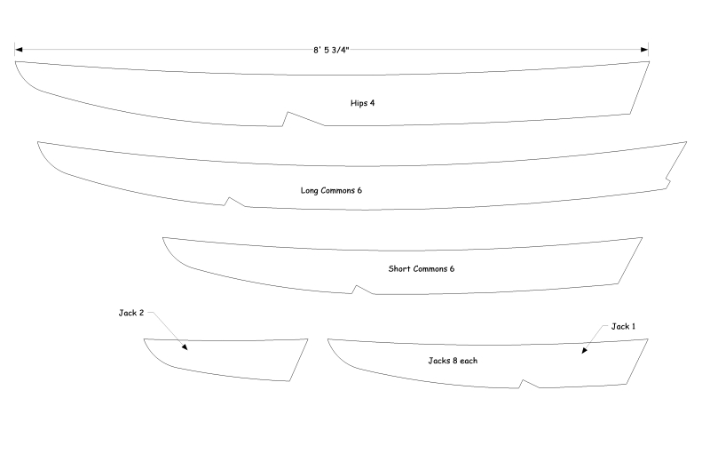
I’m having wood pieces cut by CNC, from dxf files I export from Sup. Not a problem with straight cuts, but any curves I export from Sup have all of those short straight line segments.
My question is, is there any program, or any way I can convert these
segmented curves to true curves before I hand them over to the CNC shop?These rafters are the sort of dxf files I'm exporting ..
-
Hey Joe! I don't know the answer, but I thought I'd say hi anyhow since I hadn't seen you around in ages. Hope everything is going well down in SoCal,
Chris
-
Joe
I design using ¼” steel plate and had the same problem. I started out by exporting to a cad program, than used the 3 point arc or circle to redo all the circles or arcs.
However, I found out that in steel, if I made the segments small, it didn’t matter that much to the end product.
Glad to see you back. Always like looking at your work.
Ken
-
Long time no see...

Remember that typing NNs will set a SUp Arc to NN segments while you are making it. So set it to say 100s rather than the default of 12s. That segment number is remembered for that model's session until you change it again.
You can give your SUp Arcs more segments later on by using Entity Info, this is useful if they weren't as finely segmented as needed when they were originally made.
BUT you can't change a SUp Arc's number of segments with Entity Info IF they are now part of a 3D shape, so it's good to set the number of segments early on when making the Arcs...
Remember that the segment 'length' is affected by the Arc's radius and its swept-angle. You can use this formula to estimate the number of segments you need:
number=(2*pi*radius*angle)/(360*segment_length)
you can use pi=22/7 if you don't have it on your calculator...
So if you think that 0.1" is an acceptable segmentation length and you have a quarter arc [90 degrees] that has a 12" radius, then the number of segments in that arc to give you ~0.1" 'sides' is (2pi1290)/(3600.1)=188.49... so let's make that Arc with perhaps 200s...
SUp Arcs will Export as a flat 2D plan in a 2D DXF as lots of short lines, so it's important to get their segmentation right beforehand.
However, with a 3D DXF SUp's Arcs will come in as proper CAD Arcs so their segmentation in SUp is not so critical, BUT a Curve made from a Scaled Arc etc is different - the 3D DXF takes it as a Polyline, with as many segments as the original Arc - so then it's important to up the Arc's segment count as outlined above...SUp Curves made in other ways - like Bezier - also come into a 3D DXF as Polylines so again give them lots of segments... With BZ-toolbar Bezier for example you can type 100s whilst making a Bezier Curve and it'll then have 100 segments, rather than the default of 20s... Alternatively you can select a previously made Bezier Curve and use the Edit button on the BZ-toolbar and then type say 600s to make it a super-fine Curve !
Again all of this assumes 2D forms - once you extrude any Curves into 3D shapes then the number of segments becomes frozen... Remember too, that having loads of segments when they are not needed will fill the model with edges, faces etc that will slow things down noticeably...

-
I'm surprised that SU doesn't export Curves as true curves in DXF. What if you export to DWG?
-
SUp's 3D DXF Export and 3D DWG Export gives Arcs as 'Arcs', Circles as 'Circles', BUT all Scaled Circles/Arcs and any other Curves [2D or 3D] as '3D Polylines' which then have the same number of segments as they did in SUp - making their segment-count more important...
-
Just tried doing that 3d.dxf, is this how you do it?
OK, can't upload dxf's
-
Try zipping it.
-
Yeah has been ages! Seems I'm a lurker these days.
TIG! too much info .. I know about adding segments, but I'm trying to get away from segments as we need to sand them out.
trying to understand about that 3D.dxf. Are you saying that makes true curves? How do you do that? File>Export> 3D Model.dxf?
So there isn't a program that would take my dxf/whatever files exported from SUp, and make all the curves true?
Is there any way to turn off those stupid smileys on the right when you're typing a reply!? >
-
Naw, just looked at it with DWG Truevue 2010 and it has segments, matter of fact it has extra lines too.
The curved rafter end had maybe 40 segments in SUp, in that dxf it only have a few.
-
@joe wood said:
Yeah has been ages! Seems I'm a lurker these days.
TIG! too much info .. I know about adding segments, but I'm trying to get away from segments as we need to sand them out.
trying to understand about that 3D.dxf. Are you saying that makes true curves? How do you do that? File>Export> 3D Model.dxf?
So there isn't a program that would make all the curves true?
Is there any way to turn off those stupid smileys on the right when you're typing a reply!? >In reverse order...
Smileys are there for the duration.
You can't make all Exported Curves true - you must just make them VERY segmented.
If you Export it as a 3D DXF [done just as you say, but remember to check/set the export 'options' pop-out on the dialog, just the once to get them right]: then any 2D Arcs appear as true Arcs in the DXF, BUT other Scaled Arcs and Curve types are Exported as Polylines, so the segmentation is much more important there...
You won't need 'to sand them out' IF you make the number of segments very large [the shape's sides will become so small that they'll merge into what is effectively a 'curve'] - use my formula and work out how many segments make 0.1" (or maybe even less!) for a range of typical radii - then you'll have a crib sheet to set the number of segments to a reasonable number................I see from intervening msgs that you are having problems... Are you exporting a 2D version of the rafters as 3D DXFs ?
-
This is what I've been doing. My rafter templates I make 2D, I get in the Front View, perspective off, then File> Export >2D Graphic> dxf.
In that dxf I posted, I did Export> 3D Model> dxf
In this skp, I added a bunch of segments to the bottom edges, and the curved rafter end. I didn't add more segments to the top edges because those aren't seen and don't need to sand those.
The curved rafter ends I made with 40 segments, end points are ~ 1/4" apart. I bet I should make even more. Sorry I'm not sure yet how to use that formula.
-
@joe wood said:
Is there any way to turn off those stupid smileys on the right when you're typing a reply!? >
Under the textbox - in the Options tab: "Disable smilies"
-
You probably need more segments IF they weren't Arcs***... BUT I looked at your SKP and it has just Edges and Arcs, BUT I noticed [eventually] that it also has a Face formed by these Arcs and other Edges !
If something has a Face [and your options are to Export Faces] then instead of the Edges and Arcs Exporting as just DXF Arcs and Lines, you'll get a 'Polyline Mesh' [to enclose the Face] - this is like any other type of 'Curve' Export and it then uses the 'segmentation'...
So to recap, to get pure Arcs in your Export you must have nothing more than Arcs and Edges [no Faces] to go into the 3D DXF.
So make sure any Faces are deleted and if you do have any non-Arc Curves*** then make sure they have lots of segments...
PS: Also 'Smileys are OFF' option... as TT just said...
-
Man I'm glad I posted that skp, didn't know about, not having that face in there!
Tig, what are non-Arc Curves? Are they just a series of segments (like when you Explode an arc), instead of one arc? In that skp, the bottom curves I made are arcs, and the one top curve is a non-arc curve? (the top curve is exploded)
OK, so delete that face, make the top curve one arc, and then Export> 3D Model> dxf ??
-
@joe wood said:
Man I'm glad I posted that skp, didn't know about, not having that face in there!
Tig, what are non-Arc Curves? Are they just a series of segments (like when you Explode an arc), instead of one arc? In that skp, the bottom curves I made are arcs, and the one top curve is a non-arc curve? (the top curve is exploded)
OK, so delete that face, make the top curve one arc, and then Export> 3D Model> dxf ??An Exploded Curve [an Arc or Circle is just a special sub-type of Curve] becomes just a lot of Edges.
Most of the time you do make Curves that are actually Arcs or Circles - and these Export as 3D Arcs etc - BUT you can have other types of 'Curves'.
If for example you selected all of the top pieces of Edges and then used Weld.rb on them, then it'll become a Curve [see Entity Info - it's reported as a 'Curve' NOT an 'Arc', which is itself a special sub-type of Curve] - this welded Curve is NOT editable so you are stuck with it's 'segmentation' as you welded it - so it's best to keep things as Arcs wherever possible because these Export as Arcs into a 3D DXF.
There are also other special types of Curves like Scaled-Arcs, or those that can be made with scripts like BZ-toolbar - for example, a Bezier Curve - this is a 'pure' mathematical curve - like a parabola - when you make it you can set its segment numbers [like you can with an Arc e.g. 100s] and also change then later using its toolbar 'Edit' [like Entity Info can change Arc segments that are too steppy...]
Curves are sometimes referred to as 'Polylines' - that is they are a collection of Edges 'welded' into a continuous thing. Indeed they could be any shape [e.g. a rectangle or a 3D helix] which mightn't look very 'curve-like' at all... All Curves that are NOT Arcs or Circles Export as 3D Polylines into CAD formats.Hope this helps you
-
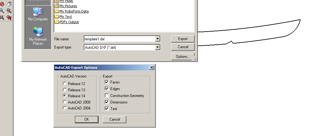
TIG, sorry but I'm not getting this right. If you take a look at this dxf, it's still segmented. I made all the rafter's curves into Arcs, and removed the one inner face,
then did Export> 3D Model> AutoCad DXF.I'll also include my revised skp again.
you say that if I Export it as a 3D DXF then any 2D Arcs appear as true Arcs in the DXF. What am I doing wrong? I'll include my Export Options.
Thanks so much for your help, got another order for a set of rafters I need cut later on in the week
")
Does it matter if I'm using SUp Ver. 5 for this??
-
I looked at your DXF and -[apart from the fact that the rafter was 'grouped' when it didn't need to be]- the Arcs are all Arcs and therefore they have NO segments. A CAD program might display them as 'segmented', BUT they are Arcs - in AutoCAD 'regenall' will stop any steppiness in the Arcs' display and draw then it perfectly as a proper Curve - this is just CAD's way of simplifying graphics in the display...
I re-exported the SKP in 7 and the 3D DXF's Arcs were fine too...
I don't think it's v5 that's causing the problems as your DXF is OK for me.
Why do you think it's 'steppy' ? Is your CAD viewer causing problems - what are you using to look at the DXF ?
Remember that if you re-import a DXF back into SUp then every Curve is made with only 12 segments by default - ALL DXFs come in like that, so yours is fine in other programs like AutoCAD BUT will always looked messed up if re-imported...
-
Oh! is that it, my viewer is displaying the segments, but the CNC machine won't?!
I'm using DWG TrueViewer 2010 as my viewer.
http://usa.autodesk.com/adsk/servlet/pc/index?id=6703438&siteID=123112right on, I'll send that new dxf to my cnc guy and see what he says!
Looks like you've saved me from alot of sanding, all my joints thank you
-
@joe wood said:
Oh! is that it, my viewer is displaying the segments, but the CNC machine won't?!
I'm using DWG TrueViewer 2010 as my viewer.
http://usa.autodesk.com/adsk/servlet/pc/index?id=6703438&siteID=123112
right on, I'll send that new dxf to my cnc guy and see what he says!
Looks like you've saved me from a lot of sanding, all my joints thank youI also looked at the DXF with DWGTrueview201o and it does 'look' steppy BUT if you do a plot preview it's a pretty smooth Arc as far as your screen resolution will allow - that's how it should arrive at the CNC...
Hopefully the CNC will take the DXF's Arcs as ice smooth Arcs - but I can't promise for someone else's bits of kit !
Hello! It looks like you're interested in this conversation, but you don't have an account yet.
Getting fed up of having to scroll through the same posts each visit? When you register for an account, you'll always come back to exactly where you were before, and choose to be notified of new replies (either via email, or push notification). You'll also be able to save bookmarks and upvote posts to show your appreciation to other community members.
With your input, this post could be even better 💗
Register Login


Advertisement