'similar' component problem
-
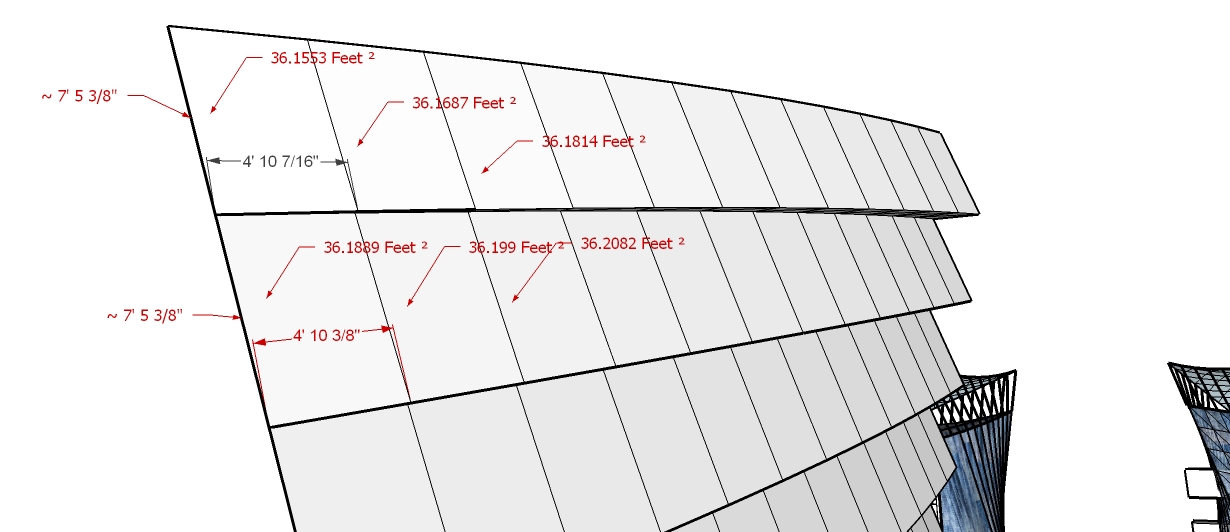
Hey guys, I'm still at odds of solving this problem, but perhaps someone could help me. Is there a way to create components to fit to similar geometries? Here's an example of what i mean.
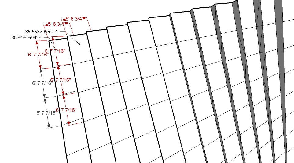
If you notice the dimensions of the two geometries are the same, but the areas are different. Each row is like that because each 'square' turns more into a 'rhombus' type shape. My question is that whether or not i would be able to create a component that can fit similar geometries (each with a slightly different dimension/angle) and still be controlled by one component. In other words - each row per column in this example can have the same component, however each column cannot not. So if there are 12 different collumns then i have to create 12 different components. In the next example the facades get a little more complex and have a greater amount of differences between each geometry, so that would be 12 times as much work (if collumn x rows = 12 x 12):)
Thank you guys for any help.
-
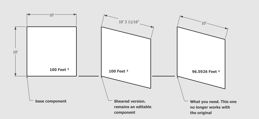
i've been thinking about this one off&on throughout the day and am concluding that -no- it's not possible to do what you want using one component to control everything.. basically, you can change the angles and shape of the original component and it will still be modifiable using the original component but once you change the area, it breaks away from the original.
that said, there is possibly a way to streamline your process (though at the end of it, you won't have only one component in various shapes).. i have some ideas to make this sort of fast but it might help to see how you're doing it right now.. i don't want to make a tut only to find out you're already doing it the way i would suggest

-
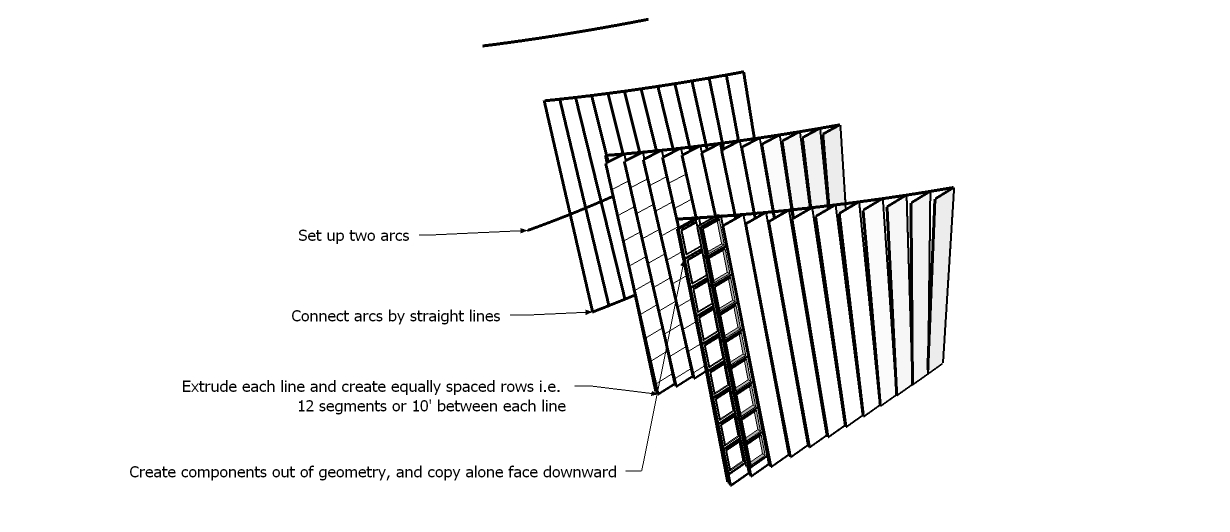
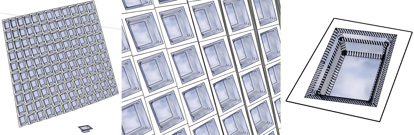
The process is quite simple. I take two arcs, deform them in a way that i see fit, connect them with straight lines, and then extrude each line along one of the vectors of the arc. Like here :
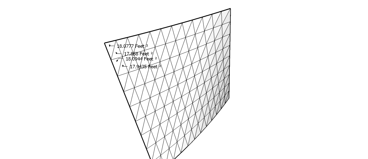
However when it comes to variable geometries, it becomes much harder - i.e. extruding arcs in the same process, or the triangulation created from say TIG's Extrude Rails by Edges as shown in here
They can be copied so long as each line is straight and not a curved line or arc (even with the same amount of distributed points on each). I'm not even talking about making similar components for triangulated surfaces.
However there is light at the end of the tunnel. I've seen it happen with Chris Fulmers script Component Stringer - where the distances between each line on an arc or curve can be different but each component can be modified by the original 'unedited' one.
-
yeah, component stringer does makes different surface areas while remaining editable so does simple scaling of an individual component..
the method i tried earlier was breaking the link between components but this .skp shows that it's possible to do what you want. just had a brain flake earlier
-
may i ask, how did you manage to scale it into a rhombus?
::edit::
oh wow, planar shearing works!!!! is it possible to do automatically adjust it in such a way so that it does that to every row/column???
p.s. apparently you can totally change the dimensions and still make it work!!!!
i edited your file
. Tell me what you thinkAnd there is one more thing, it breaks when you do taper the object. Just thought it might be a useful incite. (btw, just to be on the same track, we're both using Fredo's Scale tools right?)
By the way, i never said thank you for the help!!! Thanks alot!!
-
yeah, fredoscale.
the problem with simply shearing is that it stretches the dimensions instead of keeping them the same...

another way to make a rhombus and maintain the perimeter dimensions is by using the standard rotate tool
at the edit component level, select only the top edge and rotate it X degrees... do the same thing to the bottom edge using the same rotation value..
that will create the proper dimensions as shown in your original drawing... ExcepT, doing that will change every instance of the component instead of just one or just one row of components which is possible with shearing..the trick is figuring out a way to shear while maintaining the proper perimeter dimensions.. i found a way to do it as shown in the .skp i uploaded but the workflow is less than optimal (5or6 different things to do... scaling, copy/moving/ rotating/ scale some more etc..).. i'll think about it a little more and see if i can come up with something easier and explainable.
-
I think something like this might accomplishable through ruby - at allows component sheering <sp?>. But I don't entirely understand the question yet, or the benefit. Is this something that would be useable to more people?
Chris
-
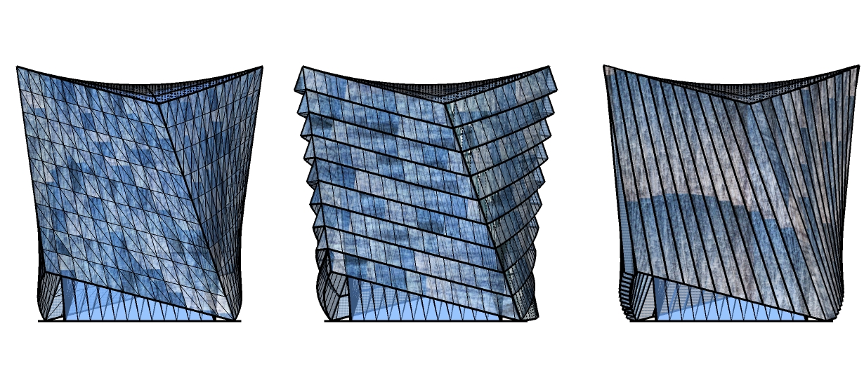
this would rival Revit or any other program in facade creation. Imagine every polygon being different that aligns/shears into position in order to become an editable component. This modification could include organic shapes!!
Heres some a work in progress on that facade. -
well pr0bka, you have 2 great ruby writers in this thread now so you better have a good pitch if you want some automation for these shapes

[namely, how can such a ruby benefit more than one user and/or circumstance]
-
As Chris says, a transformation usually rotates, scales or locates things.
However, with sufficiently clever manipulation of its transformation matrix a suitable 'shear', rotation,scale, location et al, of each instance of just one component definition might well be possible... but what exactly are 'we' trying to do here ?
-
Here are some facades that could be possible - intuitively, and very quickly, and then sent to the fabricator. You can even mix these type of designs up.
http://www.pointclickhome.com/files/web/images/07-Exterior_1_061804.jpg
http://0095b6.com/lostritto/arch470fa08/wp-content/uploads/2008/10/de-young-museum-2.jpg
http://www.architets.com/Images/Japan%202006/louisvuittonfacadedetail.jpg
http://cubeme.com/blog/wp-content/uploads/2008/04/louis-vuitton-nagoya-nagaishi-architecture1.jpg
These types of facades can then work on organic formed shapes. i.e. if one type of geometry has a shared/scaled component, it can then be manipulated all individually. Some of this can be done to the model I posted earlier already. Here's an example of a nested component that has underwent a pretty rigorous transformation in geometry.
-
Quick question, do you think driving dimensions could work on this without breaking the component? i.e. have two dimensions on two different sides control the component edges?
::Edit::
nevermind, doesn't work

-
Yeah I get it probka. That would be great for cray textured surfaces and such. Did this go anywhere ? Did anyone ever get the technique figured out?
-
@unknownuser said:
@unknownuser said:
yeah, component stringer does makes different surface areas while remaining editable so does simple scaling of an individual component..
the method i tried earlier was breaking the link between components but this .skp shows that it's possible to do what you want. just had a brain flake earlier
hey Jeff.. thanks for showing that it's possible to do that.. do you mind showing us how you did that?
oh hi Jeff.. long time no see..
sorry dude but i can't remember how i did that.. it's been a while..


Hello! It looks like you're interested in this conversation, but you don't have an account yet.
Getting fed up of having to scroll through the same posts each visit? When you register for an account, you'll always come back to exactly where you were before, and choose to be notified of new replies (either via email, or push notification). You'll also be able to save bookmarks and upvote posts to show your appreciation to other community members.
With your input, this post could be even better 💗
Register Login


Advertisement