[Plugin][$] FredoScale - v3.6a - 01 Apr 24


-
@jumpjack said:
I don't understand if this plugin can help me.
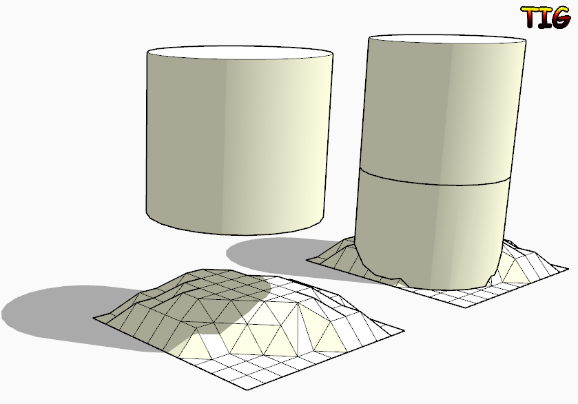
I have a non-planar surface close to a cylindrical surface; I want to extrude a region of the non-planar surface up to the cylinder to create a solid 3d joint between cylinder and the non-planar surface.
Can I use this plugin, or do I need another one?
If you want to project the bottom face of the cylinder down onto the surface then look at my ExtrudeEdgesByVector[ToObject] tool.
Edit the cylinder [group?] and copy the bottom face.
Exit the edit and use Edit>PlaceInPlace.
Select the face-copy [double-click].
Activate EEby..Object tool and pull a vertical [blue] vector down through your surface.
The face is extruded and stops on the surface...
With some finely divided surfaces the 'auto-trim' might fail, so in that case extrude through and manually intersect/delete parts.. With the simple 'toVector' version of the tool it extrudes through the surface - in that case then edit the grouped extrusion and Select its geometry and then use Intersect with Model: now Select [by fence] for the unwanted lower geometry and delete it.
-
Thanks!
-
excellent
your amazing tools are very useful
thank you very mach fredo -
NEW RELEASE: FredoScale v2.6a - 27 Nov 13
FredoScale 2.6a is a release for future Sketchup compatibility. It is advised to upgrade even if there are no functional changes.
See main post of this thread for Download.
Fredo
-
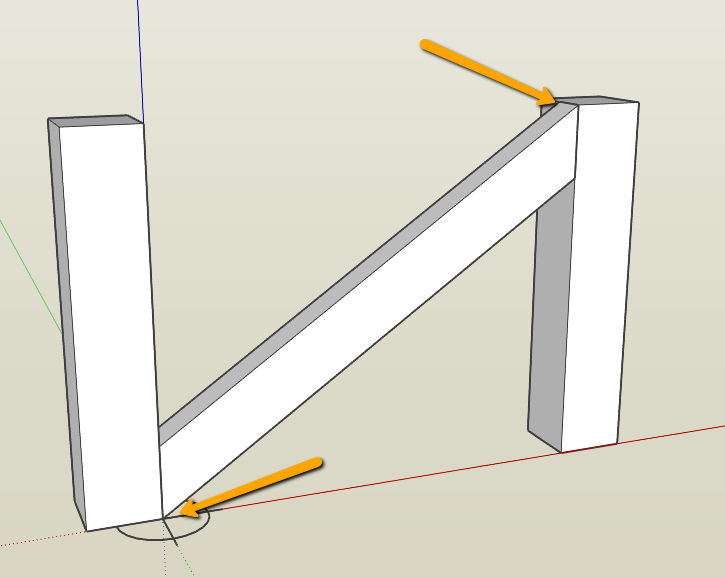
I recall a while ago the question being asked how to rotate accurately say a cross brace in a fence [see below]
I'm drawing a louvre window and want my blades to be angled in 3D to accept shadowing but only want to open the blades to the point where the top of the blade is in the same horizontal line as the bottom of the blade above. This way in elevation I achieve a clean horizontal section as well as seeing depth in shadow.
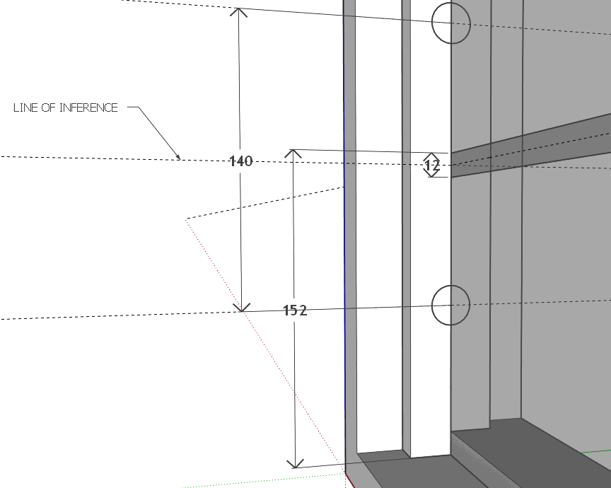
For the life of me I have been trying to rotate the lourve blades using Fredoscale rotate but do not have the option to inference to the centre of the louvre blade overlap... [middle of the 12mm overlap]
I've attached the skippy to let you see what I'm doing as well as a short video.
I expect it is something really simple that will make me look like a goose [holidays will do that...

-
Andrew, try this:
Draw a short line segment along that horizontal guideline in the vicinity of where the corner of the bottom louver should be. You can then use Rotation by Selection and Angle of Plane (the red rotate icon) to rotate and snap to the line.

Select the bottom louver.
Get the red Rotate tool from Fredoscale.
Click on the center of rotation.
Click on the top corner of the louver.
Click on the top corner again.
Move the cursor over toward the line bringing the louver corner with it.
When the line turns orange, click again to set the corner on the line.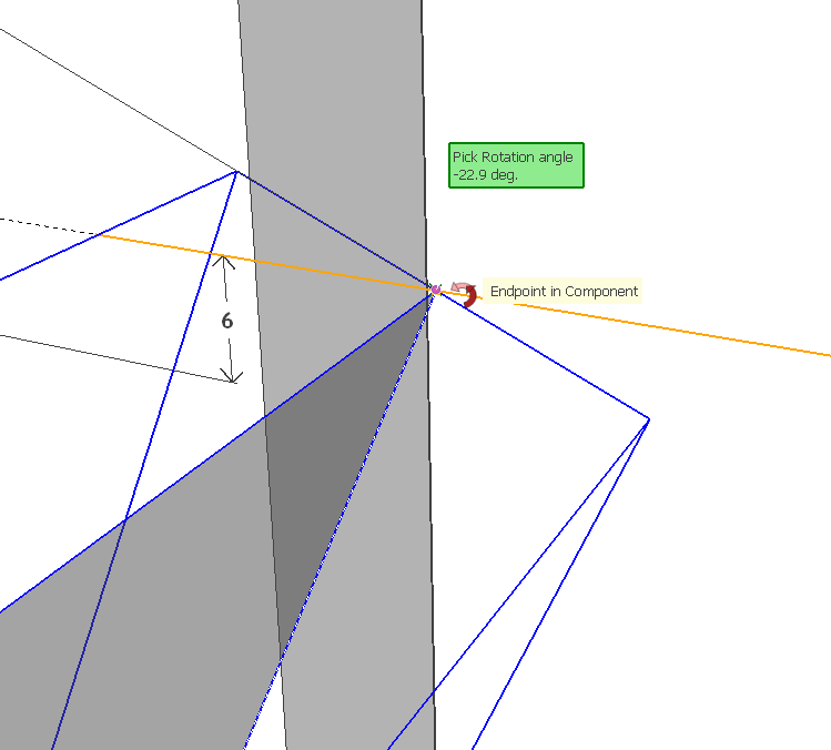
Do not repeat for the other louvers. Delete them and copy the rotated one up and make a linear array.
Delete the little short line when you've finished with it.
-
I can see what you've done here, Dave. THANKS!!!
I was going into the component and trying to inference from within.....
YOU DA MAN!!
-
Thank you.
I can see the reason for opening the component for editing because all of them would rotate at the same time. I expect you could still do that with the line but I think I'd leave the component as is and rotate the whole thing.
-
Fredo,
First of all thanks for this and all your wondeful plugins. There can't be thank enough for this contribution but I've came here bragging with an issue I've come across with Box Scaling to Target.
It is a very useful and natural way of scaling things in Sketcbup and it replaced my S key long time ago. However, today, a very simple operation gave me an unexpected result and I never seen this before. Probably it's because I hadn't noticed it or because of some setting I have changed that I'm not finding right now.
I don't know where an I failing but please take a look at this:
")

 instead of (0.75m, 0.8m). This also happens when trying to snap to an existing geometry (like that guide there).")

.")
Is there anyway I can override the snapping factor and get on with only the distance on VCB?
Thanks and best regards,
JQL
-
@JQL,
Probably a small bug which can be fixed, as the VCB should have the priority over the snapping. I'll have a look and advise
Fredo
-
Not sure I understand exactly the problem? Does it happen only in the Target mode?
I made a small change in the code to avoid roudning factors in Target mode. Since you know what is the problem and have a model to test it, could you tell me if this gives the expected result.
Just drop the attached file in Fredo6_FredoScale subfolder.
FredoScaleBox.rbThanks
Fredo
-
Fredo,
Thanks for your trouble.
I noticed random results when trying to reproduce the error today, with the old version of the file you now sent. This link is for a video that helps me describe what was happening:
https://dl.dropboxusercontent.com/u/14043066/scale%20to%20box%20random%20behaviour.avi
Funny thing is that today, Box Scale to Target was giving me trouble not along the axis but on the diagonal square.
Your fix seems to clear all randomness and so far I'm getting the expected results though, of course disregards snapping.
I'll keep using it but I'm available for anything you need to test.
Thanks,
JQL
-
JQL,
Thanks for the feedback.
If you think this is OK, then I will publish the fix.Thanks for signaling the bug.
Fredo
-
Fredo,
Thank you for your time. For me it's more important that the scale is acurate than having it snap, so the fix is more than OK... it's perfect!
Thanks again and best regards,
JQL
-
Hi Fredo:
Here is another question specifically on FredoBend:
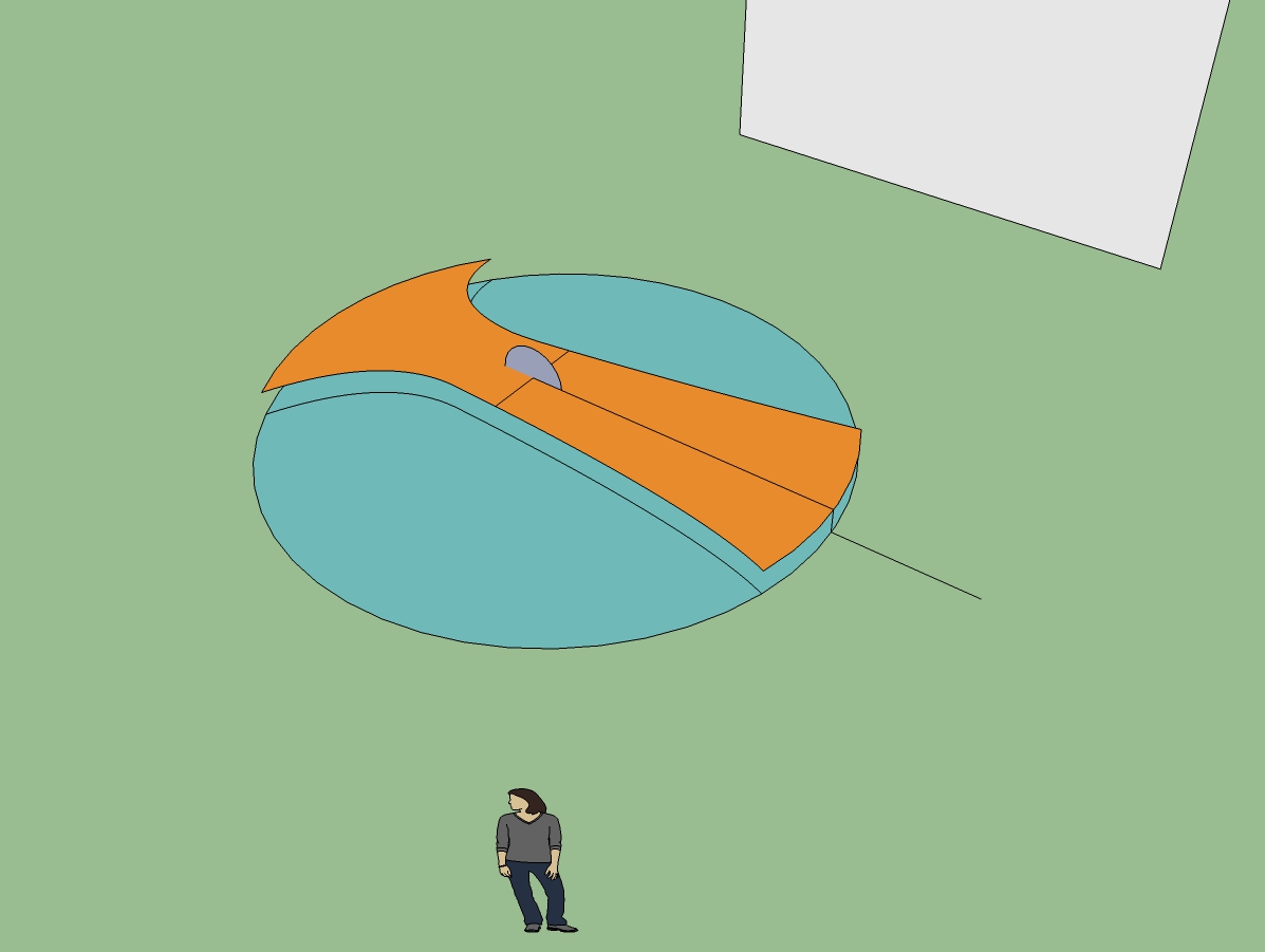
In the picture and in the skpv6 I am trying to bend the tan colored element so that its ends touch the rim of the circle on the ground plane. The whole figure is a component and the floating tan element is a group. Place the protractor at the center of the standing circle and bend the object as a group. I even placed a non grouped vertical reference line for the distance of the bend to assist.
Each time I try, I note in the Measurement Box a value of -4.5 degrees. I think I am following the tooltips correctly and visually the object seems to touch down. If I accept -4.5, the edge ends up more like -2.25, so I immediately correct that to -9 degrees and it might bend entirely the other direction, or bend-- I don't know-- maybe -1.125? The inferencing appears to act correctly, but I have to wonder if this is related to JQL's issue? The other real possibility is that I am not properly doing the procedure.
Please show me what I am missing.
-
My workaround was to overbend by a smidge, lift the end up to meet the base circle. Bend the other end-- again overbend it. Go back to the other end to set the center of rotation and rotate the other end to touch the face of the circle. If I wanted the bent piece to span to the circumference, I would have to use Scale or Stretch, which I will try next.
-
NEW RELEASE: FredoScale v2.5b - 05 Feb 14
FredoScale 2.5b fixes a bug related to the accuracy of scale factors for Box Target mode. This was signaled by JQL (see this thread).
FredoScale 2.5 requires LibFredo6 5.4 or higher.
Ideally, take this opportunity to move to LibFredo6 5.6.See main post of this thread for Download.
Fredo
-
Hi, Fredo:
See my posting above your update announcement. I updated and then went back to the model. I got a bugsplat and sent it in. This was just an attempt to overcompensate for the bend repeatedly falling short. I measured the angle for the bend with the Sketchup protractor. The value was ~-4.475 deg. Doing the bend with the inferencing I saw ~-4.5 deg.
What I did differently is set the center of the bend on the ground plane below the center of the standing circle and inferenced. Still got the extremity to go only ~half the distance. While attempting to correct this in the Measurement Box, the Bugsplat occurred.
I am sure you are busy. -
Happy new years luna 2014
-
@mitcorb said:
Hi, Fredo:
See my posting above your update announcement. I updated and then went back to the model. I got a bugsplat and sent it in. This was just an attempt to overcompensate for the bend repeatedly falling short. I measured the angle for the bend with the Sketchup protractor. The value was ~-4.475 deg. Doing the bend with the inferencing I saw ~-4.5 deg.
What I did differently is set the center of the bend on the ground plane below the center of the standing circle and inferenced. Still got the extremity to go only ~half the distance. While attempting to correct this in the Measurement Box, the Bugsplat occurred.
I am sure you are busy.I need to revisit the way target is inferenced in this tool, for sure. And post-edition too, as you crash may be related to the fact that, once bent, the shape becomes overly triangulated.
It's an old plugin, and I don't even remember if there is a trick to achieve what you wish to do.In any case, the value of the angle in the VCB is twice the actual angle measured with the Protractor. I measured 6.382 degree with the Protractor, so you need to enter 12,75 degree in the VCB.
I'll have a look when I have time.
Fredo


Advertisement