sketchucation logo sketchucation
    • Login
    ℹ️ Licensed Extensions | FredoBatch, ElevationProfile, FredoSketch, LayOps, MatSim and Pic2Shape will require license from Sept 1st More Info

    Bending shapes in Sketchup

    Scheduled Pinned Locked Moved Newbie Forum
    sketchup
    19 Posts 10 Posters 8.1k Views 10 Watching
    Loading More Posts
    • Oldest to Newest
    • Newest to Oldest
    • Most Votes
    Reply
    • Reply as topic
    Log in to reply
    This topic has been deleted. Only users with topic management privileges can see it.
    • K Offline
      kwistenbiebel
      last edited by

      I always forget what a TIN means. 😞
      Never I heard this word before in CG. Who invented it anyway? Someone on the forum?

      I would go with 'freeFormdeformation' ruby to make that form.

      1 Reply Last reply Reply Quote 0
      • D Offline
        dylan
        last edited by

        If you post the skp of the top image we can give you a more direct example probably.
        Is that twisting towards the top?

        I would initially draw the top and bottom squares, postion, then create line between these and skin. This may not be correct though, it depends on how that 3d shape really is.

        http://dmdarchitecture.co.uk/

        1 Reply Last reply Reply Quote 0
        • R Offline
          remus
          last edited by

          TIN= triangulated irregular network, dont know if it was aorund before SU, but the SU manual certainly uses it.

          http://remusrendering.wordpress.com/

          1 Reply Last reply Reply Quote 0
          • ChiefwoodworkerC Offline
            Chiefwoodworker
            last edited by

            Hi folks,

            I come from the 3D graphics chip world. In my previous life I managed the design of 3D graphics chips for ATI. In those days we called this a tessellated, or faceted or polygonal surface. I like the acronym TIN better.

            Joe....
            http://www.srww.com

            1 Reply Last reply Reply Quote 0
            • P Offline
              pav_3j
              last edited by

              @chiefwoodworker said:

              Hi folks,

              I come from the 3D graphics chip world. In my previous life I managed the design of 3D graphics chips for ATI. In those days we called this a tessellated, or faceted or polygonal surface. I like the acronym TIN better.

              so do i, i can actually pronounce TIN, tessellated would make my lil brain explode!

              pav

              Just won the 'Who is Least Competitive Championships' where trying to win will make you lose. Trying to lose makes you win which makes you lose. Not trying at all makes you lose which makes you win which makes you lose.

              1 Reply Last reply Reply Quote 0
              • Alan FraserA Offline
                Alan Fraser
                last edited by

                You can take the existing model and use the FreeForm Deformation ruby to slice it into equal vertical segments, which could then be progressively rotated...one less segment each time to create a precise bend.
                If, for instance, you applied FFD with the parameters width=2, depth=2, height=13, Subdivide=True, it will slice the model neatly into 12 equal segments. Obviously, you then just delete the group with the control points before starting to bend the stack.

                3D Figures
                Were you required to walk 500 miles? Were you advised to walk 500 more?
                You could be entitled to compensation. Call the Pro Claimers now!

                1 Reply Last reply Reply Quote 0
                • Alan FraserA Offline
                  Alan Fraser
                  last edited by

                  James,
                  You need the newer version...updated May 9th.
                  http://www.sketchucation.com/forums/scf/viewtopic.php?f=180&t=6029

                  3D Figures
                  Were you required to walk 500 miles? Were you advised to walk 500 more?
                  You could be entitled to compensation. Call the Pro Claimers now!

                  1 Reply Last reply Reply Quote 0
                  • Wo3DanW Offline
                    Wo3Dan
                    last edited by

                    redirected,

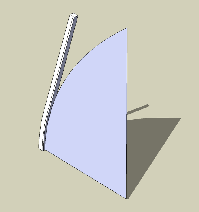
                    Here is a handmade twisted tapered bend column in attached -.skp file.

                    • rectangle 3mx3m pulled up 30m
                    • top scaled by 0,5* (with +CTRL)
                    • top rotated 15 degrees about center (midpoint diagonal)
                    • sliced by 11 section planes
                    • edges drawn on each section plane
                    • outside-diagonals to create outer faces
                    • grouped entire structure and rotated flat (horizi=ontal)
                    • applied Smoove tool (in Edit mode)&(large radius / 30m) on structures center
                    • rotated back (vertical)
                    • smooted (WIP) edges and diagonals to create outer smooth surface

                    Wo3Dan


                    TwistedColumn.skp

                    1 Reply Last reply Reply Quote 0
                    • Alan FraserA Offline
                      Alan Fraser
                      last edited by

                      You group the column, choose FFD NxN, then Subdivide ought to be right there at the bottom of the dialog box.

                      3D Figures
                      Were you required to walk 500 miles? Were you advised to walk 500 more?
                      You could be entitled to compensation. Call the Pro Claimers now!

                      1 Reply Last reply Reply Quote 0
                      • R Offline
                        remus
                        last edited by

                        Perhaps check out this thread for some more ideas: http://www.sketchucation.com/forums/scf/viewtopic.php?f=18&t=4599&p=28343&hilit=+horn#p28343

                        http://remusrendering.wordpress.com/

                        1 Reply Last reply Reply Quote 0
                        • Wo3DanW Offline
                          Wo3Dan
                          last edited by

                          @unknownuser said:

                          ....you forgot a small detail though ( I'am a stickler for detail, autocad days 😒 ),.......

                          Thanks James, I realized that later. But fortunately this simple method applies to all sorts of cross sectional shapes.
                          (It won't happen again 😄 )
                          Remus, (the link to) that horn lacks the twist. Cross sections aren't parallel -> Different approach.

                          1 Reply Last reply Reply Quote 0
                          • F Offline
                            fbartels
                            last edited by

                            Quick attempt at the general idea using a TIN beam as a starting point.

                            stick 1 template 2.jpg


                            stick 1 template 2.skp

                            1 Reply Last reply Reply Quote 0
                            • F Offline
                              fbartels
                              last edited by

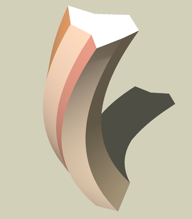
                              Playing around with this a bit more by manually bending a TIN. Tedious but definitely doable.

                              bending the line.jpg

                              But then, of course, it is really easy, if a bit less precisely controlled, with FFD.

                              having fun with ffd.jpg


                              bending the line.skp


                              having fun with ffd.skp

                              1 Reply Last reply Reply Quote 0
                              • R Offline
                                remus
                                last edited by

                                My bad, in my haste i didnt realise there was a twist in the shape 👊

                                Looks like your all brewing up some good solutions though 👍

                                http://remusrendering.wordpress.com/

                                1 Reply Last reply Reply Quote 0
                                • G Offline
                                  GreyHead
                                  last edited by

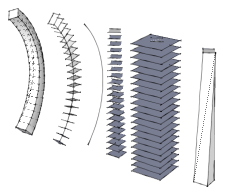
                                  Here's a version made by taking sections and realigning them to a curve. In this version the secions are normal to the curve - not sure if that's what's wanted or not.

                                  Bob


                                  13-06-2008 10-26-44.png


                                  13-06-2008 10-37-31.png

                                  1 Reply Last reply Reply Quote 0
                                  • R Offline
                                    redirected
                                    last edited by

                                    Thanks for all the help everyone!
                                    Not sure how to make things out of the TIN or use the ruby script, might try doing it with the tutorial on the horn first. I'll see how things go

                                    1 Reply Last reply Reply Quote 0
                                    • 1 / 1
                                    • First post
                                      Last post
                                    Buy SketchPlus
                                    Buy SUbD
                                    Buy WrapR
                                    Buy eBook
                                    Buy Modelur
                                    Buy Vertex Tools
                                    Buy SketchCuisine
                                    Buy FormFonts

                                    Advertisement